
Battery pack

Inactive Publication Date: 2014-06-05
TOYOTA JIDOSHA KK
View PDF1 Cites 4 Cited by
  • Summary
  • Abstract
  • Description
  • Claims
  • Application Information

AI Technical Summary

Benefits of technology

The invention relates to a battery pack with multiple battery modules that efficiently regulate temperature while minimizing pressure loss of a heat carrier used for cooling and heating the modules. This is achieved by arranging protrusions in the heat carrier flow path between adjacent modules, which meet specific conditions. The technical effect is improved heat transfer and more efficient temperature regulation in a battery pack with multiple modules.

Problems solved by technology

However, simply providing ribs that extend in the direction in which the cooling air flows on the surfaces of the cases of a plurality of single cells that make up a secondary battery pack results in the air only passing monotonically through cooling space, so a sufficient cooling effect is unable to be obtained.
Also, when protrusions are provided on the surfaces of a partition wall arranged between single cells, the flow of air inside the cooling space becomes disturbed, which does improve the cooling effect to some degree.
Moreover, in this kind of related art, when an improvement in cooling efficiency is attempted to be achieved by disturbing the flow of air inside the cooling space by providing protrusions on the surfaces of the partition wall arranged between single cells, pressure loss when air flows through the cooling space increases.
Therefore, in order to ensure the flowrate of air and maintain the heat-transfer efficiency, the capacity of means (such as a blower for example) for sending air into the cooling space must be increased, which may lead to an increase in the size of the battery pack and an increase in cost, for example.

Method used


Image

  • Battery pack
  • Battery pack
  • Battery pack

Examples


example embodiments

[0087](1. Battery Pack Structure)

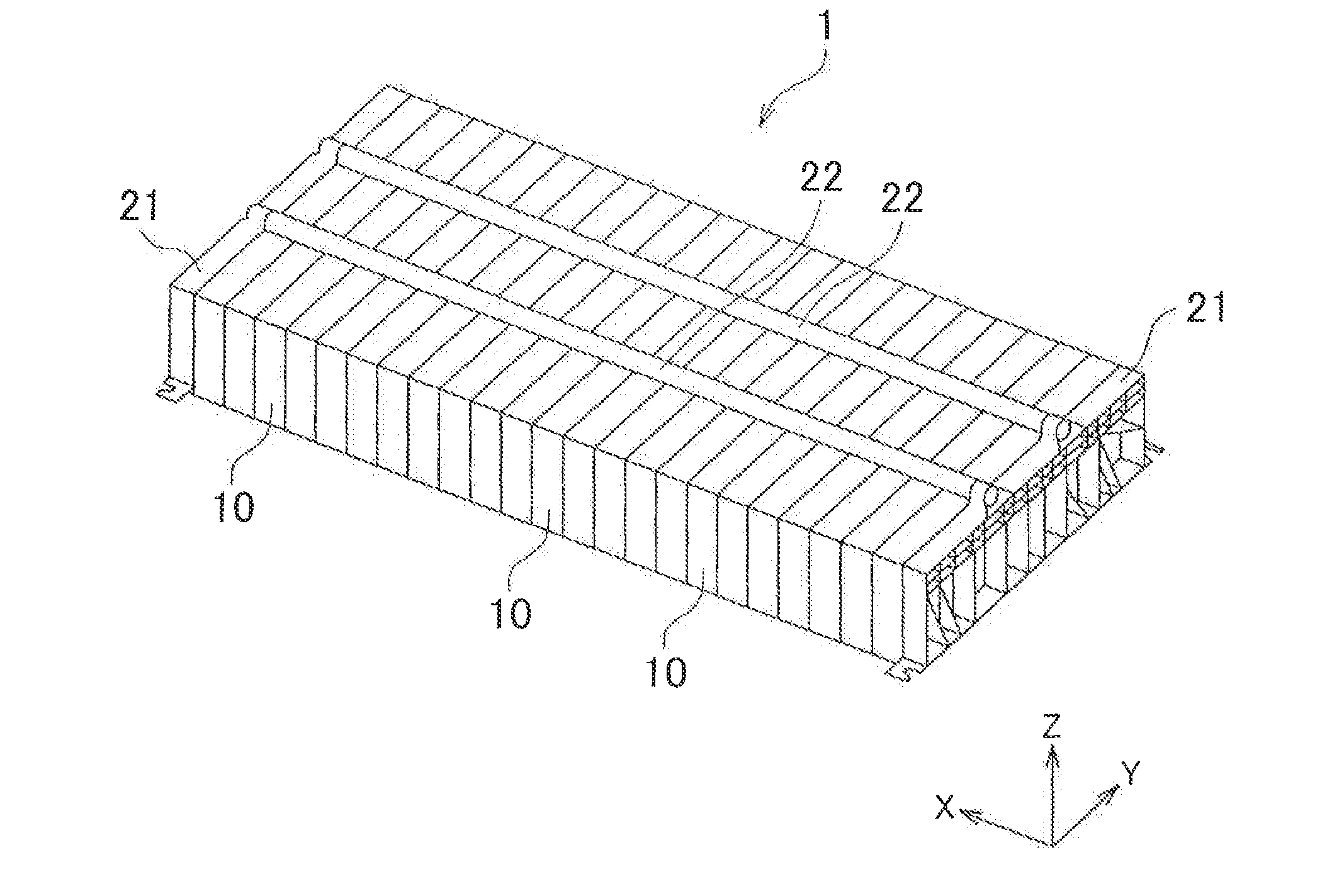
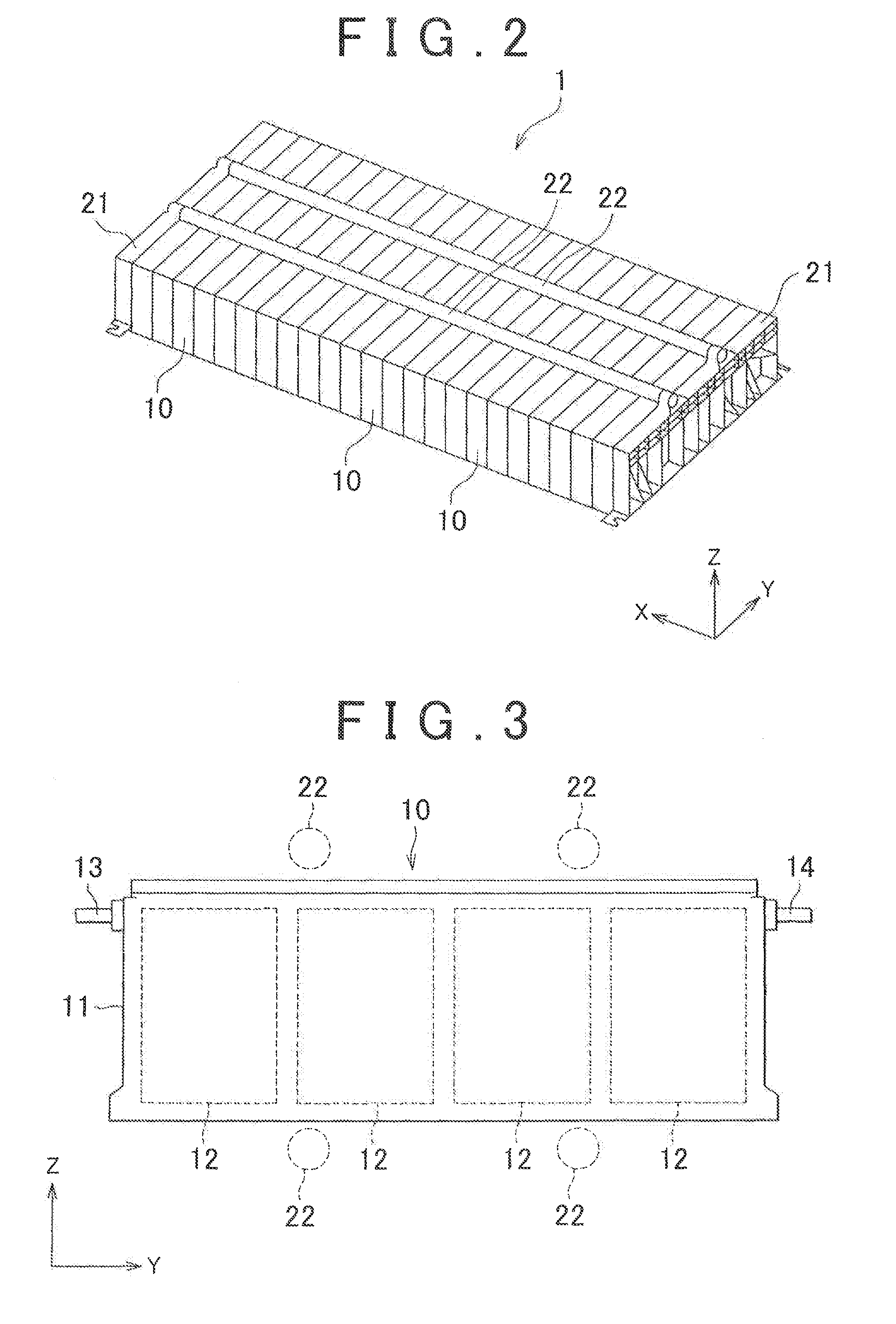
[0088]FIG. 2 is a diagram showing a frame format of the exterior of a battery pack according to one example embodiment of the invention. In FIG. 2, the X-axis, the Y-axis, and the Z-axis are all axes that are orthogonal to each other. In the battery pack 1 shown in FIG. 2, a plurality of battery modules 10 having a principal plane on the Y-Z plane are arranged lined up in the X-axis direction. A pair of end plates 21 are arranged one on each end of the battery pack 1 in the X-axis direction. A restraint rod (that corresponds to a connecting member) 22 that extends in the X-axis direction is connected to the pair of end plates 21. Restraint force is able to be applied to the plurality of battery modules 10 by fixing both ends of the restraint rod 22 to the pair of end plates 21. Restraint force is the force that squeezes the battery modules 10 together in the X-axis direction. In this example embodiment, two restraint rods 22 are arranged on an upper ...


PUM


Abstract

A battery pack includes a space as a heat carrier flow path that is formed between the adjacent battery modules; and protrusions that protrude toward an inside of the space, and that are arranged on surfaces of opposing surfaces and that define the space. The protrusions have a longitudinal direction when viewed from a protruding direction. The plurality of protrusions arranged on one surface of the opposing surfaces and the plurality of protrusions arranged on the other surface of the opposing surfaces are arranged in positions that are offset, in a flow direction of the heat carrier, from positions that oppose each other across the space. The longitudinal direction of the protrusions arranged on the one surface and the longitudinal direction of the protrusions arranged on the other surface are inclined in the same direction, with respect to the flow direction.

Description

BACKGROUND OF THE INVENTION[0001]1. Field of the Invention[0002]The invention relates to a battery pack that includes a plurality of battery modules.[0003]2. Description of Related Art[0004]In the related art, configuring a battery pack to obtain higher output voltage or the like, for example, by electrically connecting a plurality of battery modules together to form an assembled battery is known. Also, the battery modules that make up the assembled battery may each be formed by one single cell or by a plurality of single cells (that is, the battery modules that make up the assembled battery may each be formed as an assembled battery that is made up of a plurality of single cells).[0005]Such battery packs having a wide variety of structures, from those with a small capacity that are used as power supplies for small electronic devices such as telephones and laptop computers, for example, to those with a large capacity that are used as power supplies for driving apparatuses of hybrid ...

Claims


Application Information

Patent Timeline
IPC IPC(8): H01M10/60H01M2/10H01M10/613H01M10/615H01M10/6561H01M10/6563H01M10/6566H01M10/6567
CPCH01M6/5038H01M10/613H01M10/615H01M10/6551H01M10/6557H01M10/6566H01M10/60Y02E60/10
Inventor SUZUKI, TAKAMASAMURATA, TAKASHI
Owner TOYOTA JIDOSHA KK
Features
  • Generate Ideas
  • Intellectual Property
  • Life Sciences
  • Materials
  • Tech Scout
  • Unparalleled Data Quality
  • Higher Quality Content
  • 60% Fewer Hallucinations
Learn More