
Fastening system

a technology of fastening system and fastening plate, which is applied in the direction of fastening means, couplings, basic electric elements, etc., can solve the problems of rot that usually begins to set, damage the support structure of siding, and similar problems of invisible fastening systems with open joints, so as to ensure the effect of long service li

Active Publication Date: 2014-06-12
VETEDY S A R L
View PDF15 Cites 11 Cited by
  • Summary
  • Abstract
  • Description
  • Claims
  • Application Information

AI Technical Summary

Benefits of technology

The invention is a mounting device for fastening elements to rails and provides a mounting part with a base plate that can slide along the profile of a rail and hold the element securely. The mounting part also has toothed surfaces that work with the rails to secure a safe and accurate installation. The device can be used on horizontal or vertical surfaces and ensures inter-board ventilation and longevity. The invention allows for quick and precise installation of sidings with minimal screws and invisible fastenings.

Problems solved by technology

As the sidings are insufficiently ventilated, rot usually begins to set in and damages the support structure of the siding.
Other systems for invisible fastening with open joints have similar problems.
Nevertheless, the fastenings are made from profiled grooves on the sides of the boards, which causes rainwater to collect, promoting rot and the proliferation of algae and insects on the structure.
The wood may also buckle since, owing to capillary action, the finishing board touches the siding which is full of the moisture which enters the wood.
This causes the hygrometry on the lower face of the finishing board to increase in relation to the upper face, which causes the surface wooden strips to sag and become less aesthetically pleasing.

Method used


Image

  • Fastening system
  • Fastening system
  • Fastening system

Examples


Embodiment Construction

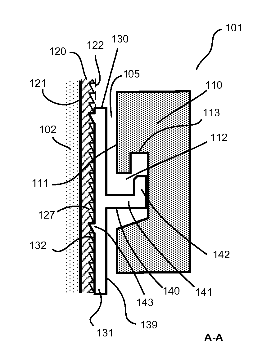
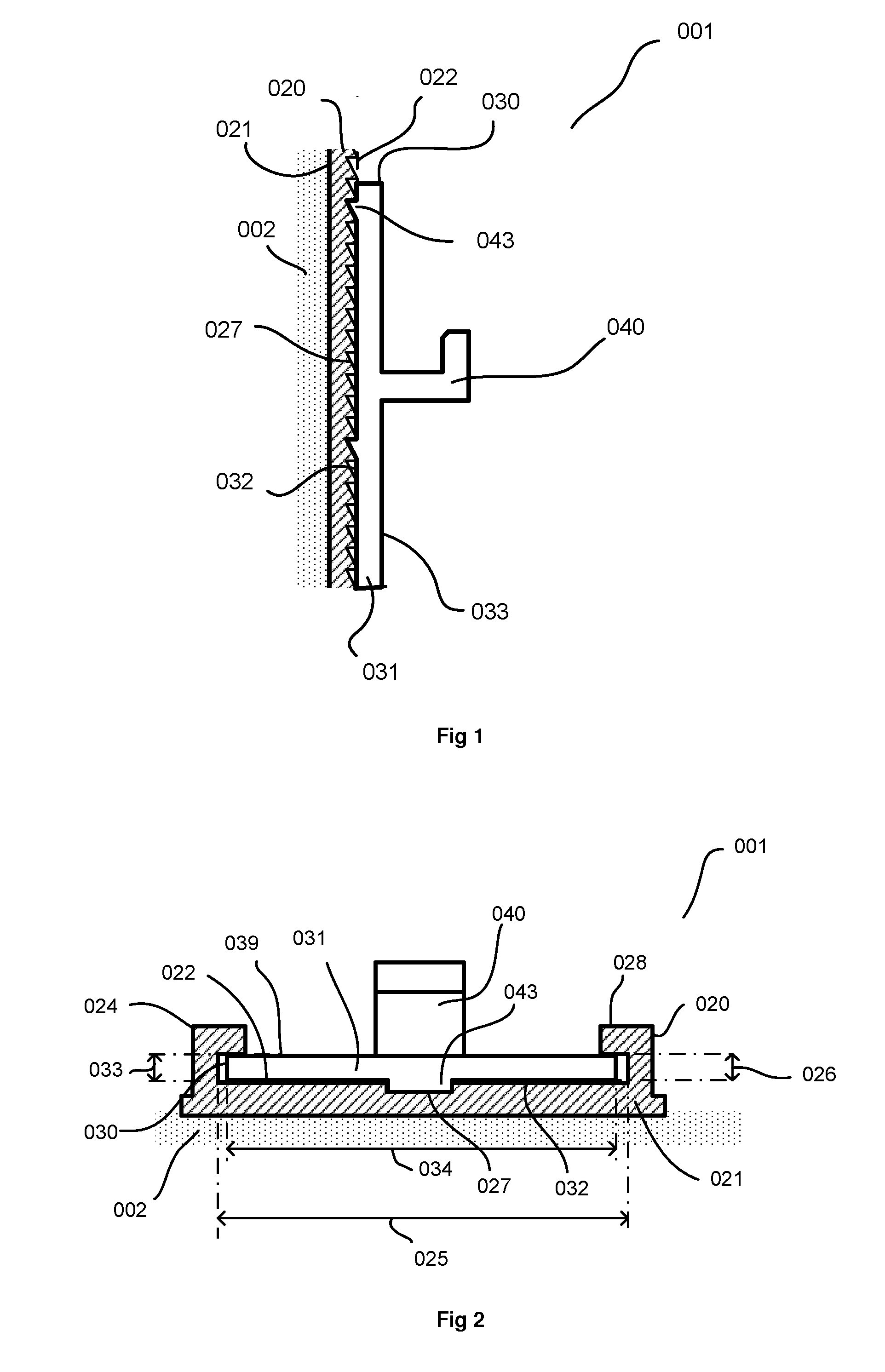
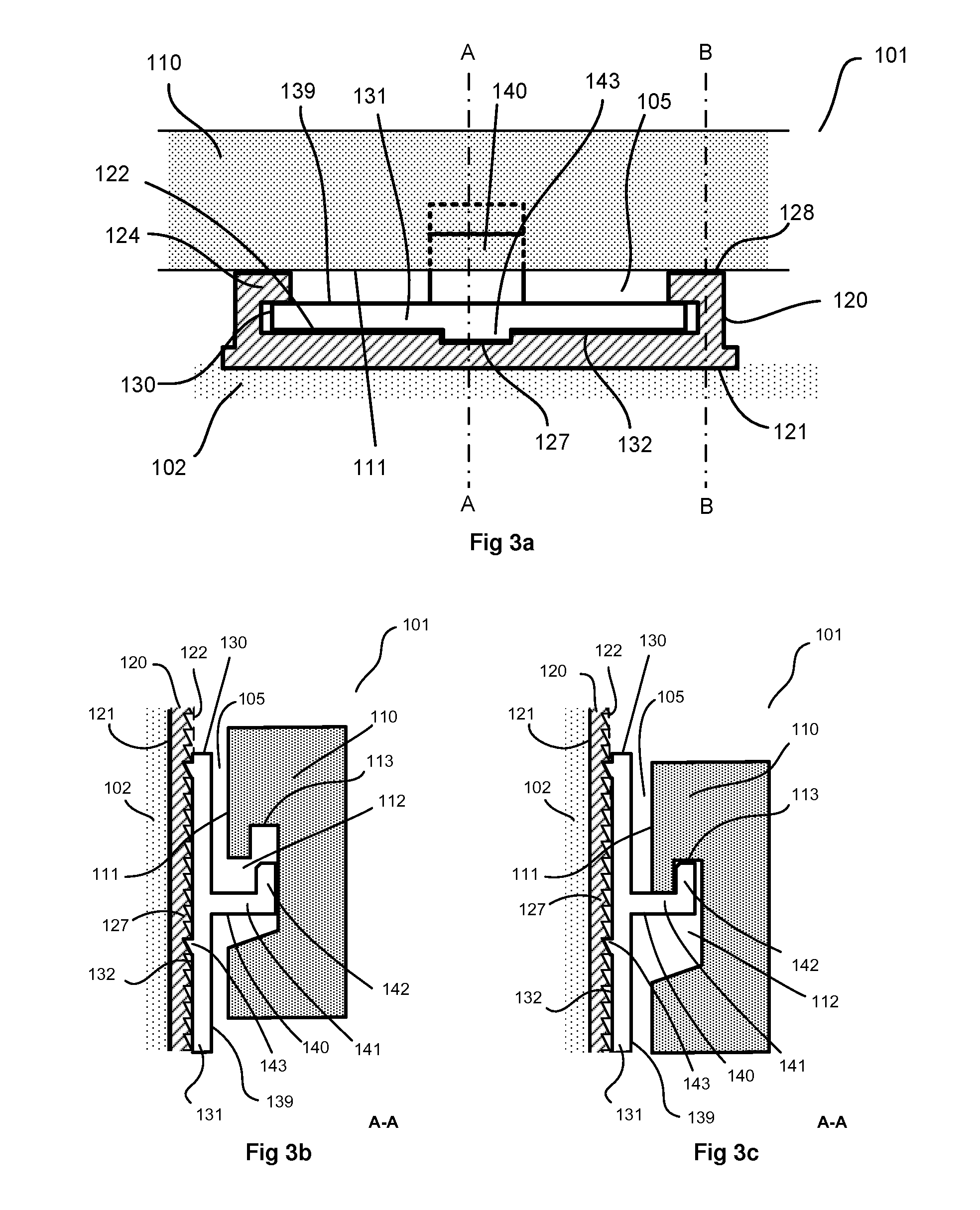
[0049]The invention will be described below by way of an advantageous embodiment and with reference to the accompanying drawings. In the drawings, similar numerals represent similar concepts in different embodiments of the invention. For example, the fastening arrangement according to the present invention is denoted by numerals 001, 101, 201.

[0050]With reference to FIG. 1 and FIG. 2, the arrangement 001 according to the present invention comprises at least one fastening rail element 020 having a C-profile 024. The lower face 021 of the rail advantageously contacts a support 002. The rail 020 is preferably fastened to the support 002 by screwing. The support 002 corresponds for example to a wall to be covered with a siding. The rail element 020 is typically orientated vertically on the support. As shown in FIG. 2, the C-profile has an opening which is orientated towards the upper face 022 of the rail and defines a profile width 025 and a profile height 026.

[0051]The arrangement 001 ...


PUM

PropertyMeasurementUnit
widthaaaaaaaaaa
widthaaaaaaaaaa
heightaaaaaaaaaa

Abstract

The present invention relates to an arrangement for fastening visible elements and in particular an arrangement for mounting sidings. According to the present invention, rapid and precise installation is ensured, together with extended durability of the siding with invisible fastenings.

Description

TECHNICAL FIELD[0001]The present invention relates to an arrangement for fastening visible elements and in particular an arrangement for mounting sidings in any material.BACKGROUND OF THE INVENTION[0002]The present invention belongs to the field of fastening visible elements on planar surfaces. External flat roofs or facades are commonly made from boards, for example wooden strips, installed on a framework which in particular is made up of wall plates previously fastened to the floor or to the wall.[0003]At present there are wooden siding systems, known as tongue and groove systems, without open joints between the siding strips. Systems of this type propose a method involving wall plates fastened on watertight insulation (generally a rubber-like web) on which the siding boards are fastened by nailing into tongues provided for this purpose. The adjacent board fits into the tongue via a groove specially profiled for this purpose. As the sidings are insufficiently ventilated, rot usual...

Claims


Application Information

Patent Timeline
Patent Type & Authority Applications(United States)
IPC IPC(8): E04F13/08
CPCE04F13/081E04F13/0823E04F15/02044E04F2015/02072E04F13/0819Y10T403/70Y10T29/4995E04F13/0816E04F13/0801
Inventor DEUMER, PATRICK
Owner VETEDY S A R L
Learn More