
Polishing apparatus and polishing method

Active Publication Date: 2014-06-12
EBARA CORP
View PDF13 Cites 11 Cited by
  • Summary
  • Abstract
  • Description
  • Claims
  • Application Information

AI Technical Summary

Benefits of technology

The present invention relates to a polishing apparatus and method for preventing polishing liquid from getting attached to the surface of various parts around a polishing table, which can cause scratches on the substrate surface. The invention aims to provide a polishing apparatus with anatomizer cover that prevents liquid left on the surface from getting inside the atomizer cover and contaminating the polishing surface. Additionally, the invention provides a top ring head cover that prevents the polishing liquid from contaminating the top ring head and the polishing surface.

Problems solved by technology

If the dried polishing liquid falls onto the polishing table, the fallen matters may cause a scratch on the substrate.
Once the polishing liquid is attached to and dried on the surfaces of the constituent parts, it is difficult to rinse off the dried polishing liquid with the cleaning liquid.
Moreover, if the dried polishing liquid is deposited repeatedly, the dried polishing liquid may fall onto the polishing pad, thus causing a scratch on the substrate.
In addition, since the atomizer cover has a number of corners where the liquid is likely to remain, it is generally difficult to clean an external surface of the atomizer cover with a cleaning liquid.
If the liquid containing the polishing liquid is attached to and solidified on the atomizer cover, the solid matter may fall onto the polishing surface, thus contaminating the polishing surface.
It is difficult to completely prevent the scattered polishing liquid from flowing into the top ring head cover.
Thus, the polishing liquid may enter the interior of the top ring head cover and stay there, thus contaminating the top ring head cover or the top ring head.
Further, the polishing liquid may drop from the top ring head cover onto the polishing surface, thus contaminating the polishing surface.

Method used


Image

  • Polishing apparatus and polishing method
  • Polishing apparatus and polishing method
  • Polishing apparatus and polishing method

Examples


Embodiment Construction

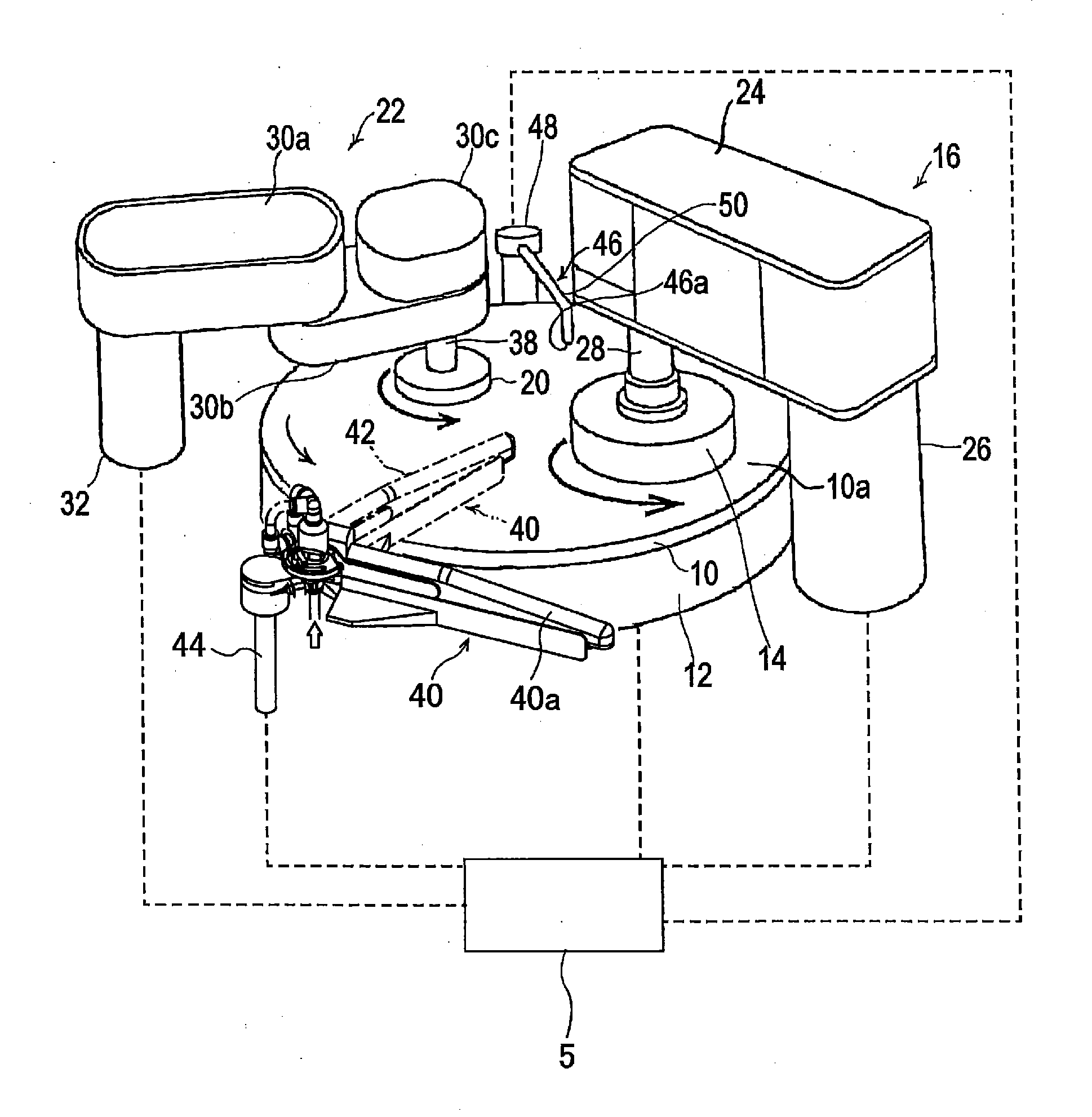
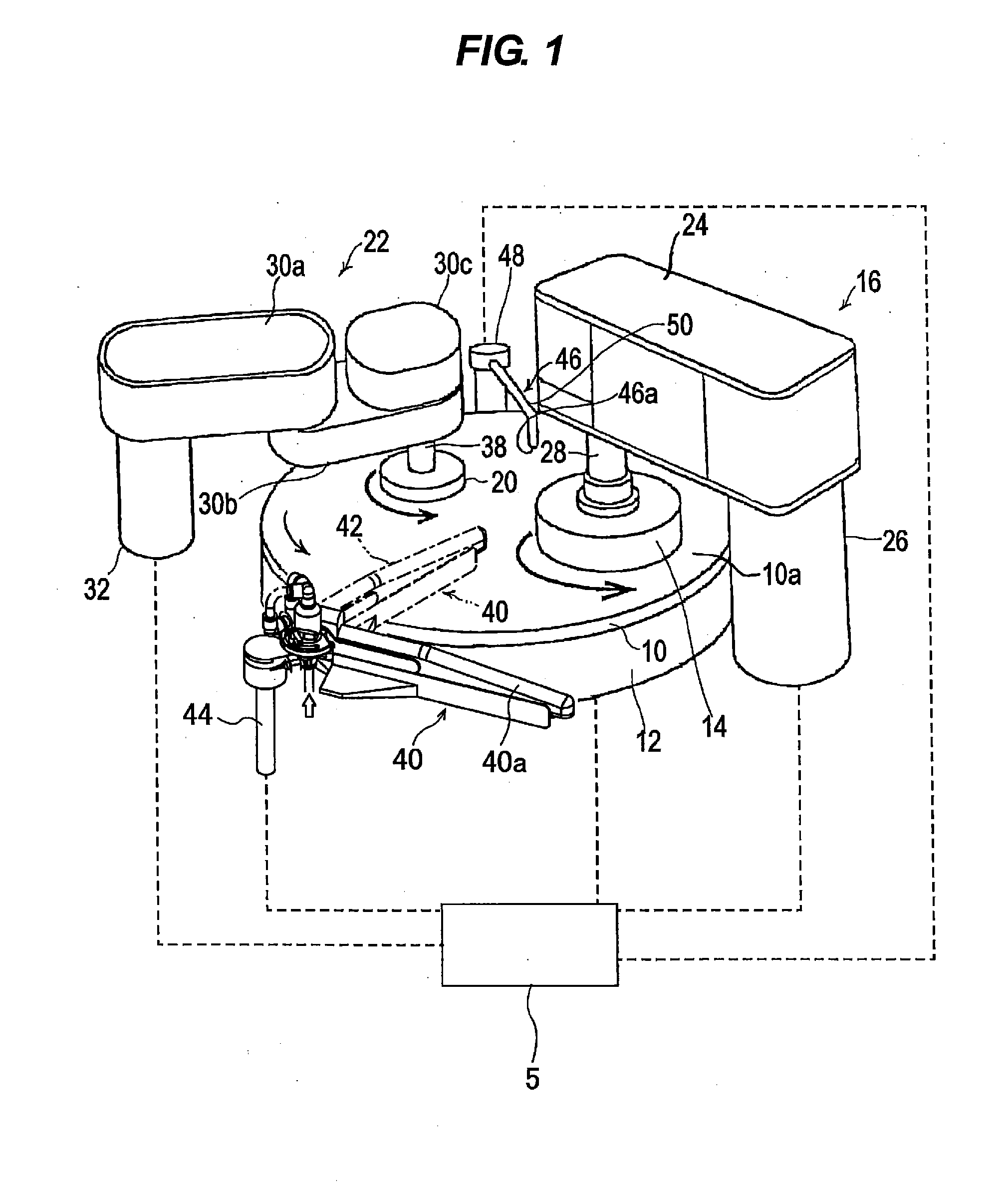
[0056]Embodiments of the present invention will now be described with reference to the drawings. FIG. 1 is a perspective view of a polishing apparatus according to an embodiment of the present invention. FIG. 1 shows the polishing apparatus when a top ring 14 is in a polishing position above a polishing table 12 and a dresser 20 is in a dressing position above the polishing table 12. Depiction of spray nozzles is omitted in FIG. 1.

[0057]As shown in FIG. 1, the polishing apparatus includes a polishing pad 10 whose upper surface serves as a polishing surface 10a, a polishing table 12 with the polishing pad 10 attached to an upper surface thereof, a top ring head 16 having a top ring 14 for bringing a substrate (polishing object), such as a wafer, into sliding contact with the polishing surface (upper surface) 10a of the polishing pad 10 to polish the substrate, and a dresser head 22 having a dresser 20 for conditioning (or dressing) the polishing surface 10a of the polishing pad 10. T...


PUM


Abstract

A polishing apparatus includes: a rotatable polishing table for supporting a polishing pad having a polishing surface; a top ring head having a top ring; a top ring head cover surrounding the top ring head; a dresser head having a dresser configured to dress the polishing surface; a dresser head cover surrounding the dresser head; a spray nozzle configured to spray a cleaning liquid onto an upper surface of the top ring and an outer surface of the top ring head cover when the top ring is in the substrate transfer position; and a spray nozzle configured to spray a cleaning liquid onto an outer surface of the dresser head cover when the dresser is in the retreated position.

Description

CROSS REFERENCE TO RELATED APPLICATIONS[0001]This document claims priorities to Japanese Patent Application Number 2012-240394, filed Oct. 31, 2012 and Japanese Patent Application Number 2012-242951, filed Nov. 2, 2012, the entire contents of which are hereby incorporated by reference.BACKGROUND OF THE INVENTION[0002]1. Field of the Invention[0003]The present invention relates to a polishing apparatus and a polishing method, and more particularly to a polishing apparatus and a polishing method for polishing and planarizing a surface of a polishing object (substrate), such as a wafer, while preventing the formation of scratches on the surface of the polishing object, caused by a polishing liquid that has been scattered and dried.[0004]The present invention also relates to a polishing apparatus, and more particularly to a polishing apparatus for polishing and planarizing a surface of a polishing object (substrate), such as a wafer, while preventing a polishing liquid from contaminatin...

Claims


Application Information

Patent Timeline
IPC IPC(8): B24B53/017B24B37/32B24B37/10
CPCB24B53/017B24B37/32B24B37/102B24B37/04
Inventor UMEMOTO, MASAOSONE, TADAKAZUAIZAWA, HIDEOKOSUGE, RYUICHIERIGUCHI, MASAAKI
Owner EBARA CORP
Features
  • Generate Ideas
  • Intellectual Property
  • Life Sciences
  • Materials
  • Tech Scout
  • Unparalleled Data Quality
  • Higher Quality Content
  • 60% Fewer Hallucinations
Learn More