Collision avoidance during controlled movement of image capturing device and manipulatable device movable arms

a technology of manipulable devices and robot arms, which is applied in the field of robot arms, can solve the problems of confusion and unintended consequences, damage to arms, and difficulty in collision avoidance, and achieve the effect of minimizing a cost function

Active Publication Date: 2014-06-12
INTUITIVE SURGICAL OPERATIONS INC +1
View PDF4 Cites 142 Cited by
  • Summary
  • Abstract
  • Description
  • Claims
  • Application Information

AI Technical Summary

Benefits of technology

[0043]In some examples, the controller is configured to determine which one of the first and second robot arms is to be configured in one of its plurality of possible configurations to avoid a collision with the other one of the first and second robot arms by processing differences between current configurations of the first and second robot arms and their respective pluralities of possible configurations to minimize a cost function. In some examples, the controller is configured to determine which one of the first and second robot arms is to be configured in one of its plurality of possible configurations to avoid a collision with the other one of the first and second robot arms by processing required joint movements of the first and second robotic systems to move from their current configurations to others of their respective pluralities of possible configurations to minimize a cost function.
[0044]Consistent with some embodiments is a method for avoiding collisions between first and second robot arms. The first robot arm holds a manipulatable device having a working end. The second robot arm holds an image capturing device for capturing a plurality of images of the working end of the manipulatable device from which a three-dimensional computer

Problems solved by technology

When the robot arms are operating within close proximity to each other, there is a possibility that the arms may collide with one another and by so doing, cause damage to the arms.
However, when the robot arms are independently operated, collision avoidance may be much more challenging.
When a plurality of robot arms is controlled by a plurality of contro

Method used


Image

  • Collision avoidance during controlled movement of image capturing device and manipulatable device movable arms
  • Collision avoidance during controlled movement of image capturing device and manipulatable device movable arms
  • Collision avoidance during controlled movement of image capturing device and manipulatable device movable arms

Examples


Embodiment Construction

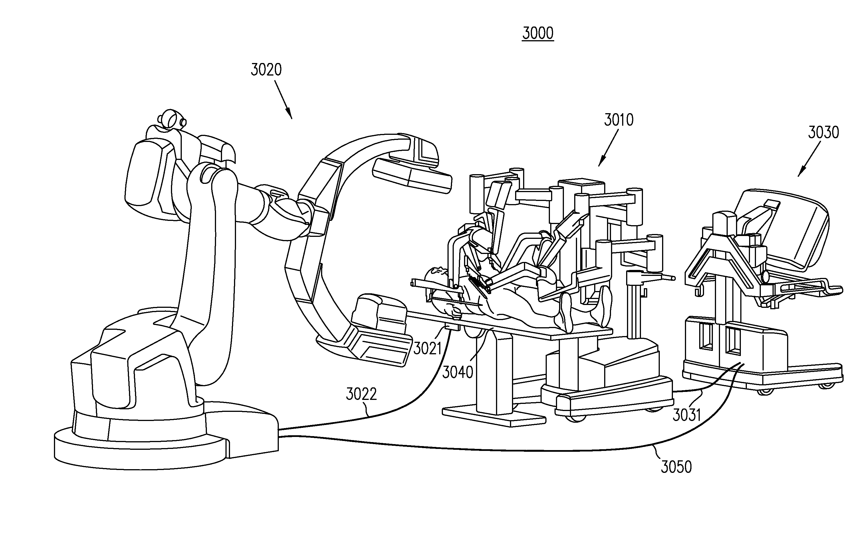
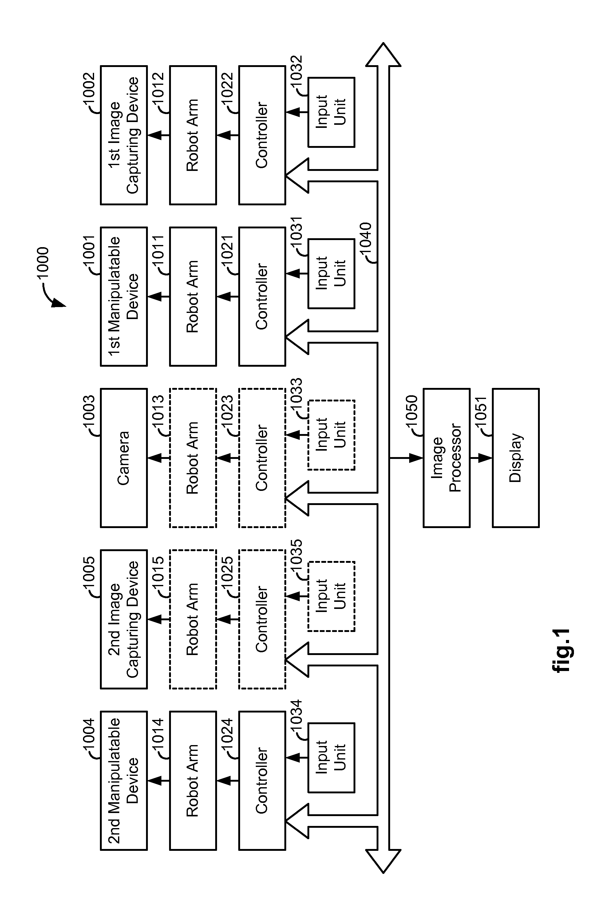
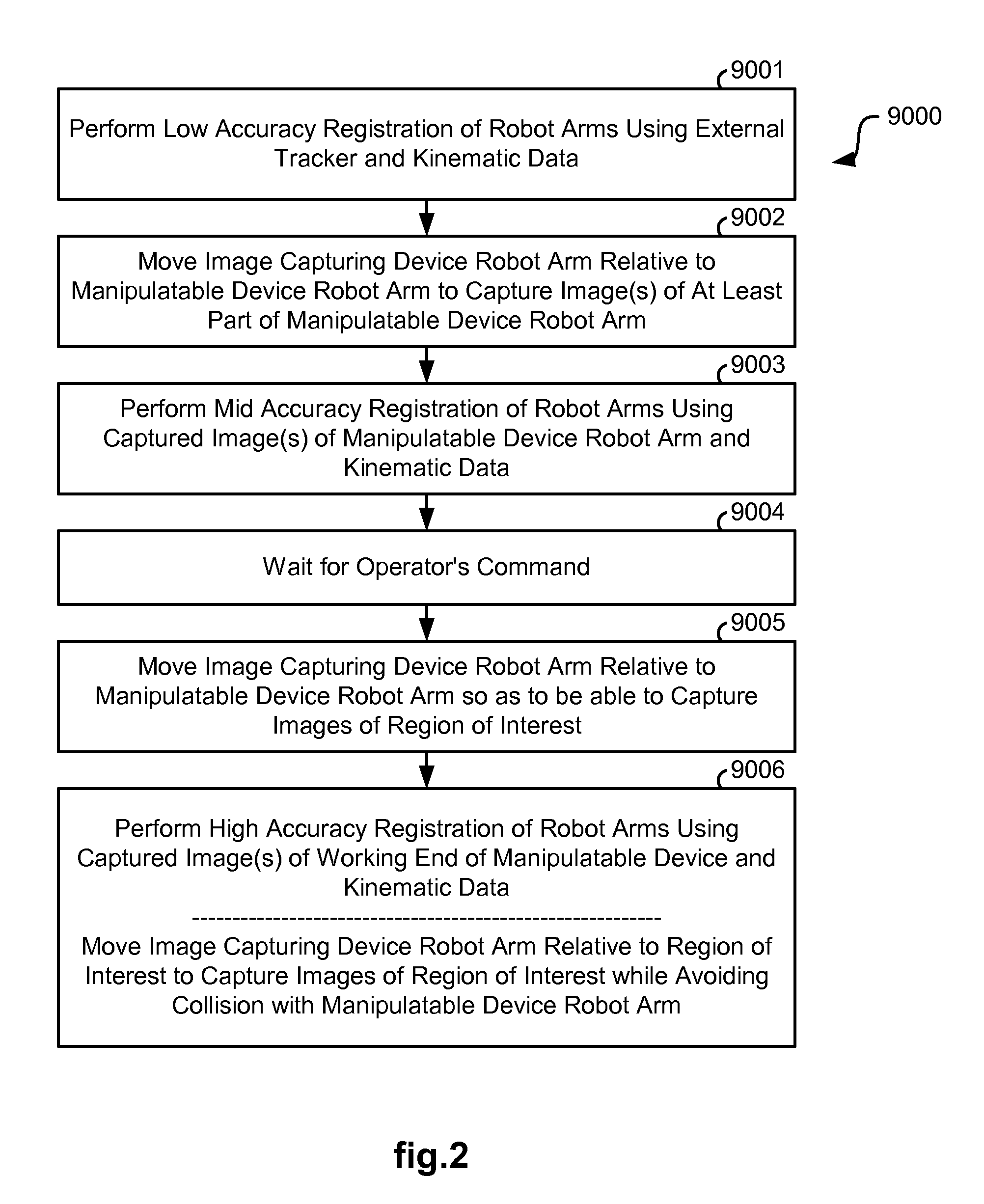
[0063]FIG. 1 illustrates, as an example, a block diagram of various components of a robotic or computer-assisted system 1000 in which methods 2000, 2500, and 4000 are implemented for automatically avoiding a collision between two or more robot or movable arms. FIG. 2 describes a multi-step approach to registration of robot or movable arms. FIGS. 3, 4 are provided to describe the methods 2000, 2500 which are generally applicable to independently operated robot or movable arms. FIGS. 5-7 are provided to describe the method 4000 which is generally applicable to controlling movement of an image capturing device robot or movable arm though a controller which is controlling a manipulatable device robot or movable arm. Examples of the robotic system 1000 in which the methods 2000, 2500, and 4000 may be used are described in reference to FIGS. 8-15. FIGS. 8-12 are provided to describe a robotic or computer-assisted system 3000 using a Patient-Side Cart 3010 with multiple robot or movable ar...


PUM


Abstract

A system and method for movement control includes a controller coupled to a computer-assisted surgical device having a first movable arm coupled to a manipulatable device having a working end and a second movable arm coupled to an image capturing device. The controller is configured to receive first configurations for the first movable arm; receive second configurations for the second movable arm; receive a plurality of images of the working end from the image capturing device; determine a position and an orientation of the working end; determine a first movable arm position and trajectory for the first movable arm; determine a second movable arm position and trajectory for the second movable arm; determine whether motion of the movable arms will result in an undesirable relationship between the movable arms; and send a movement command to the first or second movable arm to avoid the undesirable relationship.

Description

CROSS-REFERENCE TO RELATED APPLICATIONS[0001]This application claims priority to provisional application No. 61 / 735,170, filed Dec. 10, 2012, entitled “Collision Avoidance During Controlled Movement of Image Capturing Device and Manipulatable Robot Arms”, which is incorporated herein in its entirety by reference.FIELD OF THE INVENTION[0002]The present invention generally relates to robotic systems and in particular, to collision avoidance during controlled movement of image capturing device and manipulatable device robot arms.BACKGROUND OF THE INVENTION[0003]Robotic systems and computer-assisted devices often include robot or movable arms to manipulate instruments for performing a task at a work site and at least one robot or movable arm for supporting an image capturing device which captures images of the work site. When the robot arms are operating within close proximity to each other, there is a possibility that the arms may collide with one another and by so doing, cause damage ...

Claims


Application Information

Patent Timeline
IPC IPC(8): A61B19/00
CPCA61B2034/2055A61B6/4458A61B2090/376A61B2034/2059A61B2034/2065A61B2090/378A61B6/102A61B6/4441Y10S901/02Y10S901/47A61B34/30B25J9/1697A61B90/361B25J9/1676A61B2090/306A61B2090/371A61B2017/00216A61B1/00149A61B1/00009A61B1/00087A61B1/05A61B1/00183A61B34/20A61B90/37
Inventor AZIZIAN, MAHDISORGER, JONATHANBLOHM, LUTZNIEBLER, CHRISTINEKUNZE, HOLGER
Owner INTUITIVE SURGICAL OPERATIONS INC
Why Eureka
Try Eureka