Flexible electric flyswatter with shape memory capabilities
Inactive Publication Date: 2014-06-19
GORDON IV NATHAN LOUIS
View PDF6 Cites 12 Cited by
Summary
Abstract
Description
Claims
Application Information
AI Technical Summary
This helps you quickly interpret patents by identifying the three key elements:
Problems solved by technology
Method used
Benefits of technology
[0011]A unique feature of this electric flyswatter is that the frame is flexible and will allow for striking on a surface without cracking or breaking. The flexibility of the frame is accomplished by utilizing shape memory polymers where there is a grooved track within the frame to encase the rods. The oppositely charged rods within the frame are comprised of electrically conducting shape memory metals
Problems solved by technology
It is generally well known that flies within a building often land on flat surfaces, such as a wall or table, where they cannot be swatted by a traditional electric fly swatter due to their ridged outer frame and ridged grid assembly.
These
Method used
Image
Click on the blue label to locate the original text in one second.
Reading with bidirectional positioning of images and text.
Examples
Embodiment Construction
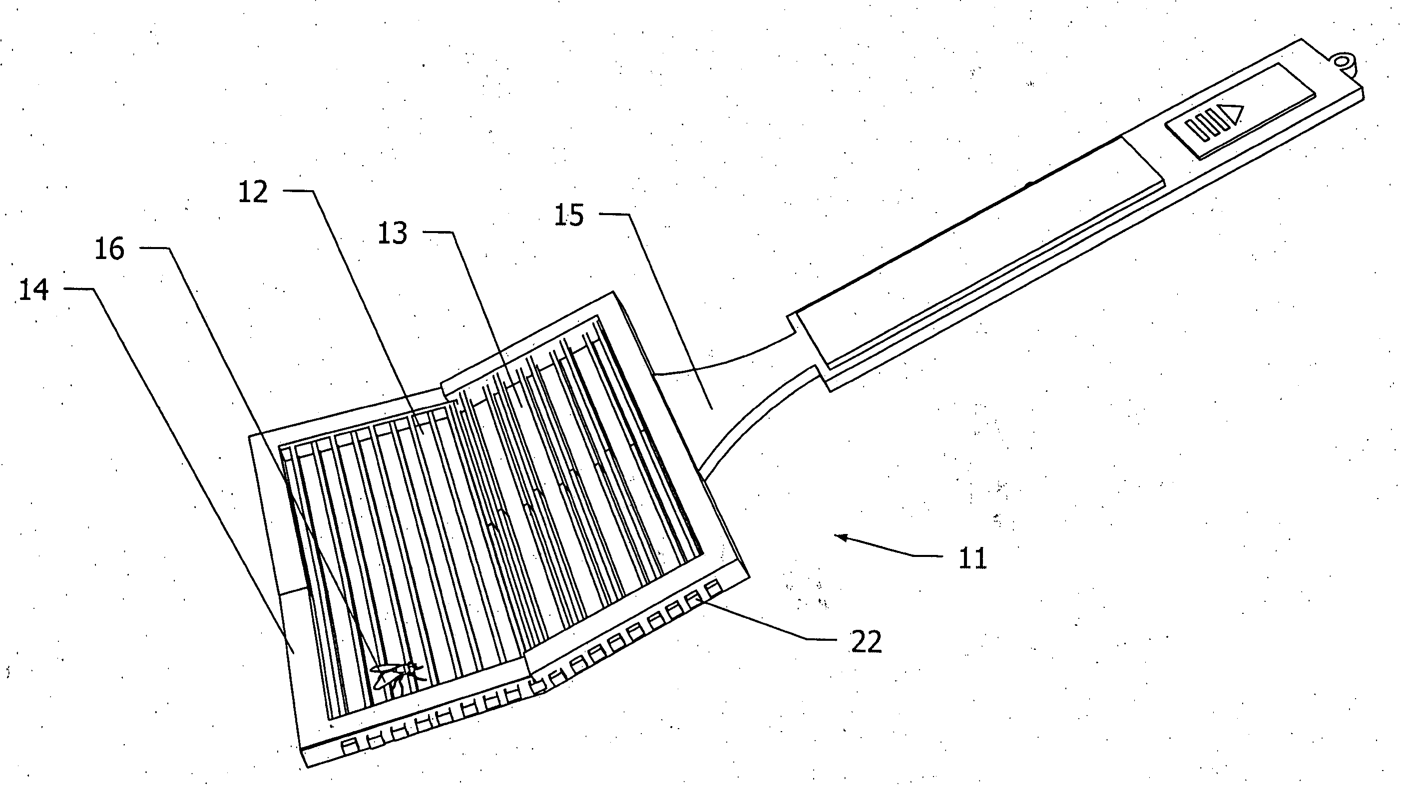
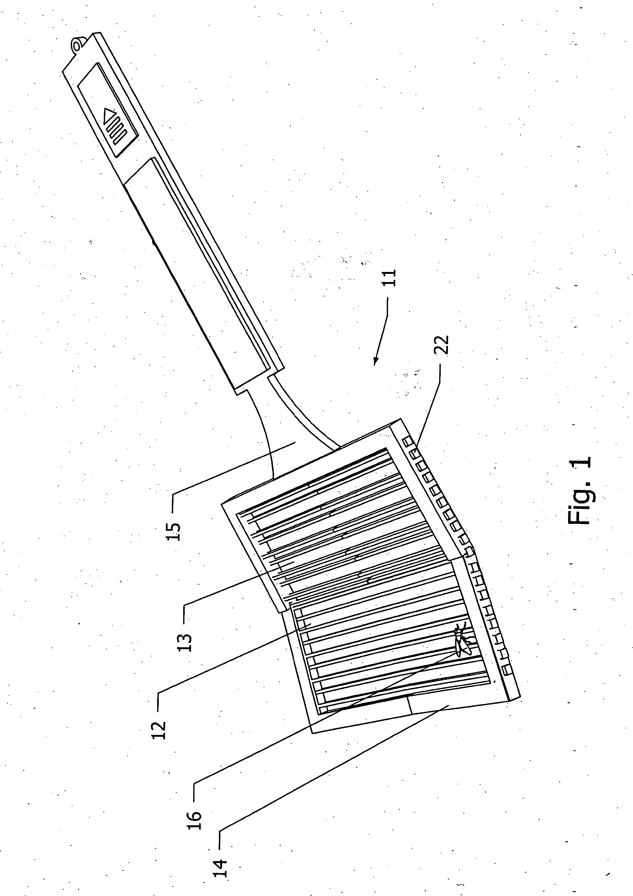
[0052]Referring to the drawings, and first to FIG. 1 an embodiment of the flexible electric flyswatter of this invention is identified with the numeral 11. The flexible electric flyswatter contains three basic portions,—that is, a single layer grid 12 (where the grid 12 comprises oppositely charged rods 13 of shape memory material), the grid 12 is encased within a flexible frame 14, where the flexible frame 14 is connected to a handle 15. At the distal and proximal ends of rod 13 are end-caps 22 to prevent a rod from escaping from the flexible frame 14. The flexible electric flyswatter 11 is shown in a deformed position which occurs upon the impact of striking and electrocuting a fly 16 on a hard surface.
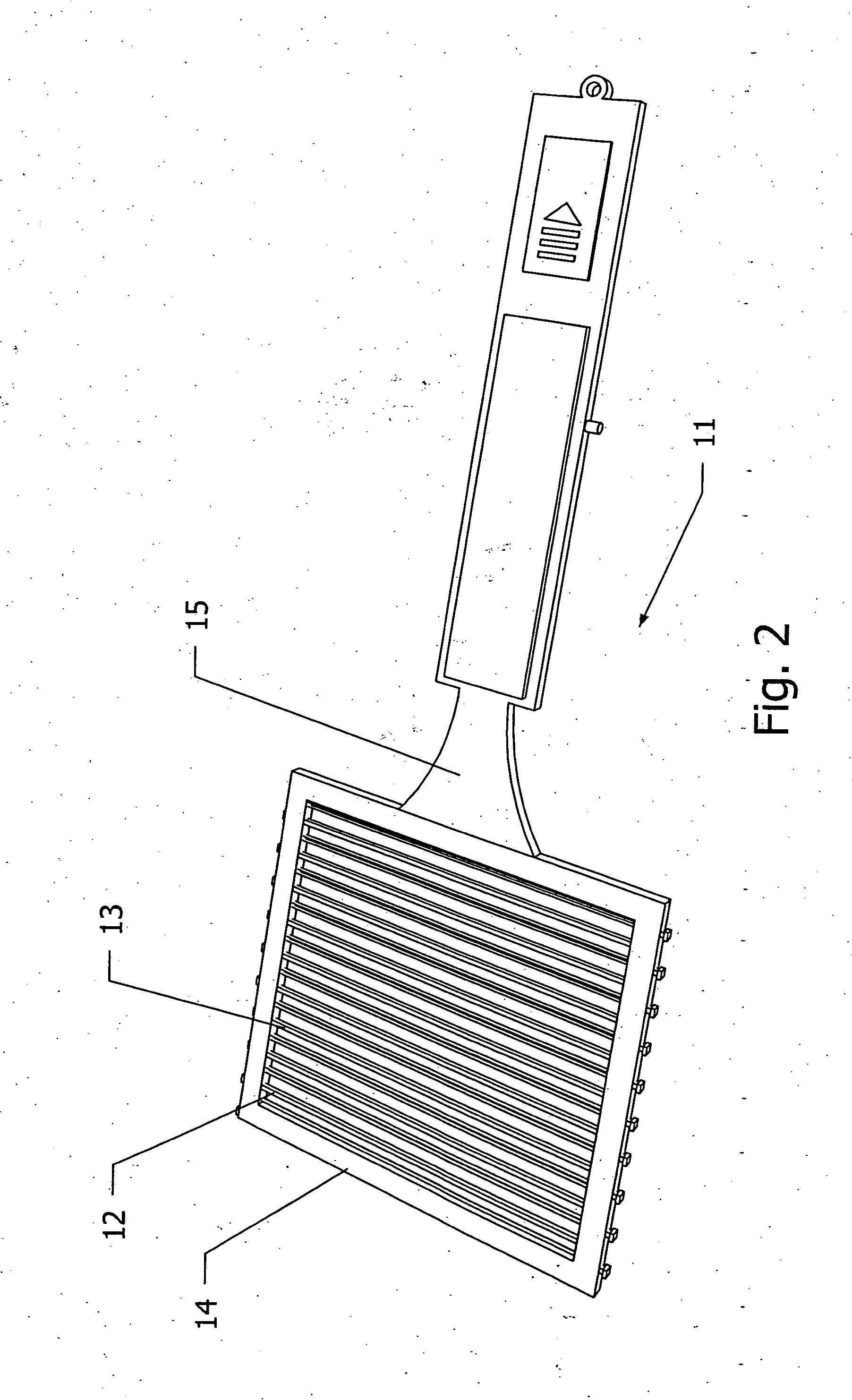
[0053]FIG. 2 is a perspective view of a flexible electric flyswatter 11 where a single layer grid 12 comprising oppositely charged rods 13 of shape memory material are encased within a flexible frame 14 and attached to handle 15 and the flexible electric flyswatter 11 is shown in a ...
PUM
Abstract
A flexible electric fly swatter comprising a grid of electrically conducting shape memory materials encased within a flexible frame for striking against and electrocuting a fly on a surface or in the air. The single layer grid has odd and even rods oppositely charged where both the frame and the grid return back to their original shape after being struck. An alternate embodiment of this invention is a flexible electric fly swatter comprising two or more meshes in parallel of electrically conducting shape memory materials that are fastened together with connecting-spacers to allow a gap between the top mesh and the bottom meshes such that when a fly touches the meshes the circuit is completed and the fly is electrocuted. Also included in this invention is a spring-pivot-hinge fastened between the dorsal part of the handle to the proximal part of the frame or meshes.
Description
CROSS-REFERENCE TO RELATED APPLICATIONS [0001]This application claims the benefits of provisional patent application Ser. No. 61 / 797,103 filed 2012 Nov. 29 by the present inventor.BACKGROUNDPrior Art[0002]The following is a tabulation of some prior art that presently appears relevant:7,739,830June 2010Wells43 / 137; 43 / 132.17,540,112June 2009Crenshaw43 / 137; D22 / 1246,055,767May 2000Carter43 / 134, 136, 1375,531,436October 1994Merrick43 / 137; 132.1; 1125,269,092December 1993Cobble43 / 134, 135, 136, 1374,910,909March 1990Johnson43 / 1374,905,408March 1990Wu43 / 136, 1374,617,754October 1986Miley43 / 1373,905,146September 1975Ralston43 / 137; D22 / 20; D88 / 23,673,730July 1972Hcgenberger43 / 1372,934,851May 1960Grish43 / 1372,881,554October 1958Laine43 / 1371,879,495November 1932Renwick1,179,303April 1916HanlonNON-PATENT LITERATURE DOCUMENTS [0003]Fly-killing device, wikipedia.org (Nov. 20, 2013 11:35 PM), http: / / en.wikipedia.org / wild / Flyswatter[0004]Dynazap extendable insect zapper, dynatrap.com (Nov. 20, 20...
Claims
Application Information
Patent Timeline
Application Date:The date an application was filed.
Publication Date:The date a patent or application was officially published.
First Publication Date:The earliest publication date of a patent with the same application number.
Issue Date:Publication date of the patent grant document.
PCT Entry Date:The Entry date of PCT National Phase.
Estimated Expiry Date:The statutory expiry date of a patent right according to the Patent Law, and it is the longest term of protection that the patent right can achieve without the termination of the patent right due to other reasons(Term extension factor has been taken into account ).
Invalid Date:Actual expiry date is based on effective date or publication date of legal transaction data of invalid patent.