
Water meter systems and methods

Active Publication Date: 2014-06-19
CAPSTONE METERING
View PDF8 Cites 27 Cited by
  • Summary
  • Abstract
  • Description
  • Claims
  • Application Information

AI Technical Summary

Benefits of technology

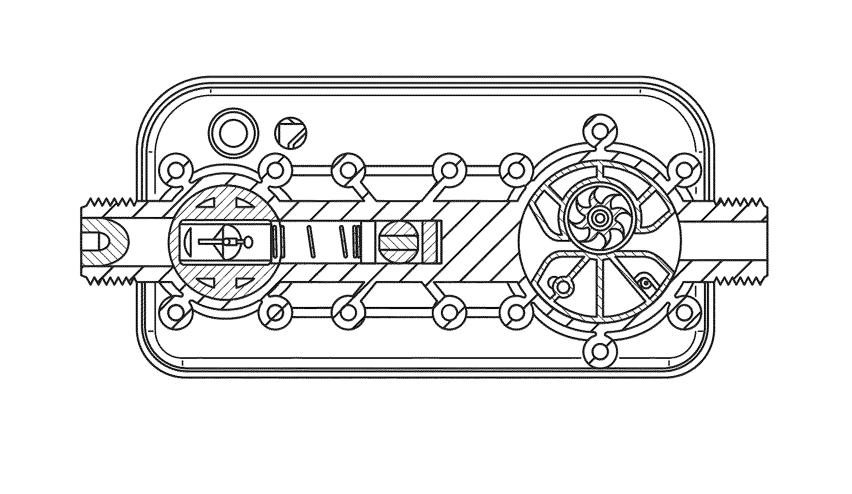
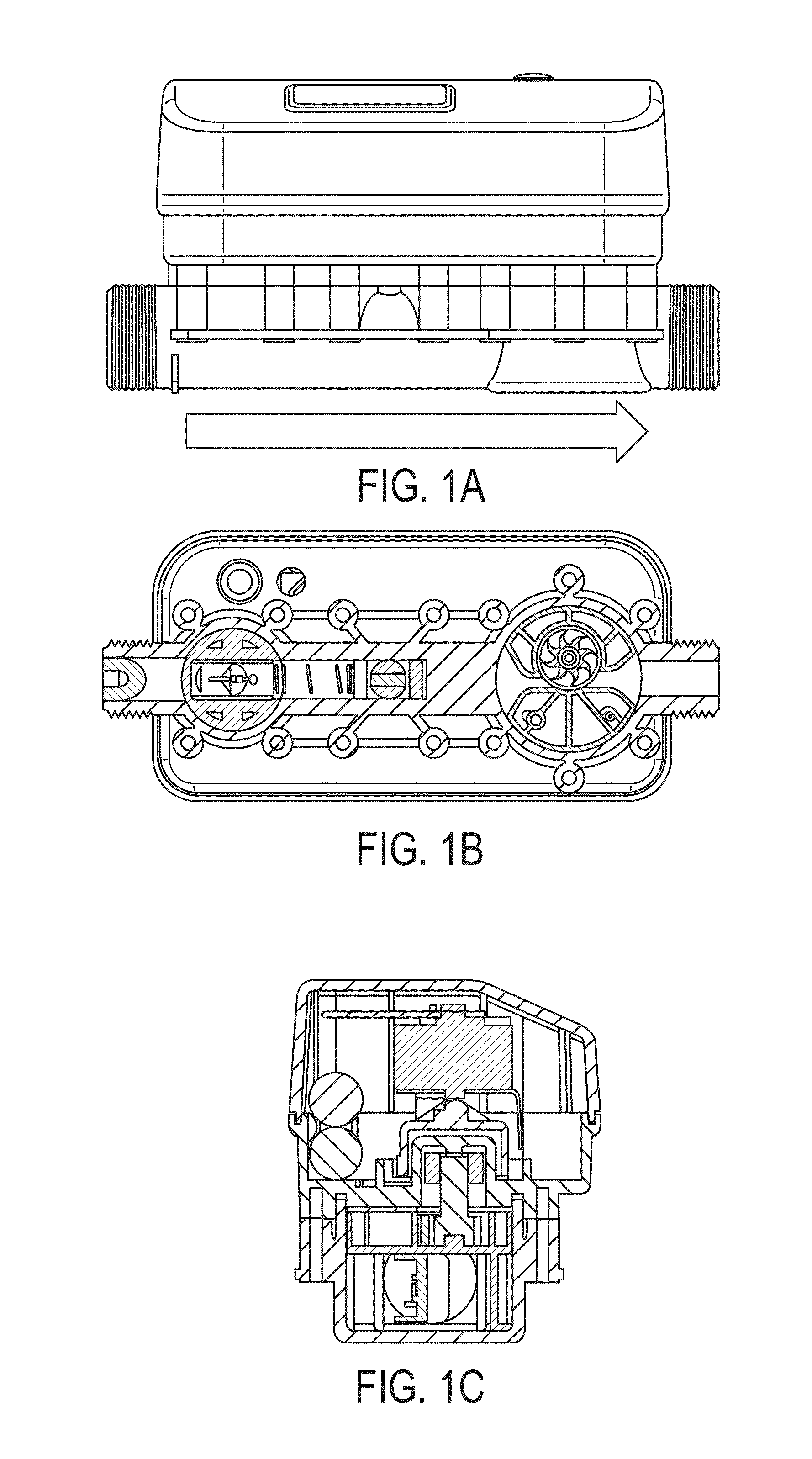
The patent describes a counting wheel that can rotate smoothly and capture energy from the flow of fluid. Its blades are curved to improve energy collection and maximize contact with the water. Structural rigidity is added to the blades with a central rig disk, and the back sides of the blades are closed and curved away from the flow of water to minimize resistance and improve measurement at low flow. Overall, the design of the counting wheel provides better performance and accuracy in measuring fluid flow.

Problems solved by technology

To the extent that conventional water meters can transmit usage data, these meters are typically capable of transmitting data only relatively infrequently due to power issues and other constraints.
For example, this transmission distance is generally limited, requiring field technicians to either read the meter directly or from a relatively short distance away.
If the power source is rechargeable, it may not be easily be recharged because water meters are not typically connected to an external power source.
Further, after 3-5 years of operation, wear and tear may require meters to be recalibrated.
Worn meters may over or under read the amount of fluid passing through the meter and it may require significant effort and expense to systematically check and calibrate individual meters in a given service area.
Additionally, the dimension of a typical water meter do not necessitate placement of water meters in the walls of a building or the like.

Method used


Image

  • Water meter systems and methods
  • Water meter systems and methods
  • Water meter systems and methods

Examples


Embodiment Construction

[0020]Refer now to the drawings wherein depicted elements are not necessarily shown to scale and wherein like or similar elements are designated by the same reference numeral through the several views.

[0021]Referring to the drawings in general, it will be understood that the illustrations are for the purpose of describing particular implementations of the disclosure and are not intended to be limiting thereto. While most of the terms used herein will be recognizable to those of ordinary skill in the art, it should be understood that when not explicitly defined, terms should be interpreted as adopting a meaning presently accepted by those of ordinary skill in the art.

[0022]It is to be understood that both the foregoing general description and the following detailed description are exemplary and explanatory only, and are not restrictive of the invention, as claimed. In this application, the use of the singular includes the plural, the word “a” or “an” means “at least one”, and the use...


PUM


Abstract

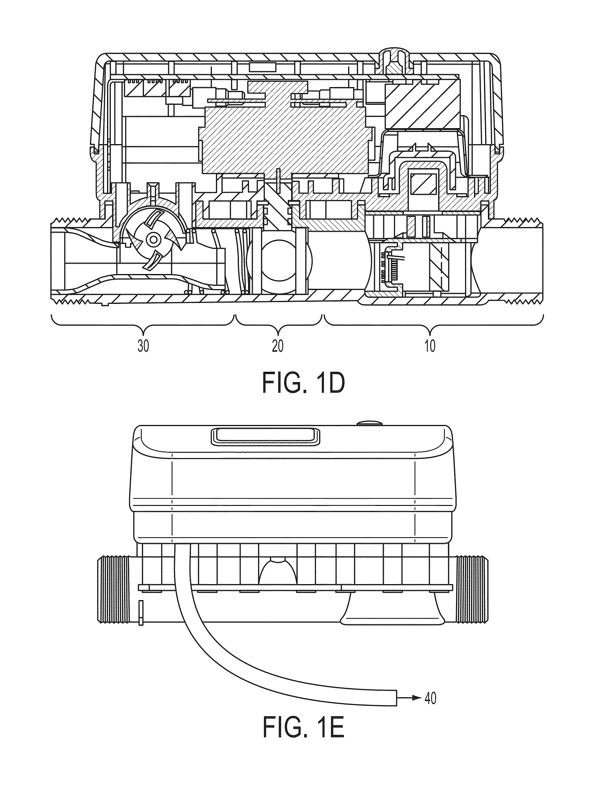
A linear water meter system may include a metering system, a ball valve, a power generation system, a wireless communication system, or a combination thereof. The linear water meter system may provide a linear pathway through the meter that minimizes pressure loss in the system. Two pathways may be provided through the power generation system. One pathway may be utilized to generate power, and the other pathway may provide a bypass that can be utilized to maintain a desired water pressure level in the system.

Description

RELATED APPLICATIONS[0001]This application claims the benefit of U.S. Provisional Patent Application No. 61 / 739,363, filed on Dec. 19, 2012, which is incorporated herein by reference.FIELD OF THE INVENTION[0002]This invention relates to water meter systems and methods. More particularly, to water meter systems and methods that provide a linear design, an counting wheel suitable for low flow metering, self-generating energy, a bypass flow path, and / or rechargeable energy storage.BACKGROUND OF INVENTION[0003]Fluid meters are utilized to measure volume of fluid usage. For example, in some countries, water meters are used at each residential and commercial building in a public water supply system. To the extent that conventional water meters can transmit usage data, these meters are typically capable of transmitting data only relatively infrequently due to power issues and other constraints. For example, this transmission distance is generally limited, requiring field technicians to eit...

Claims


Application Information

Patent Timeline
IPC IPC(8): G01F15/00
CPCG01F1/06G01F1/07G01F1/363G01F1/40G01F7/00G01F15/00
Inventor WILLIAMSON, JAMES SCOTTKILLMEYER, JOHN MICHAELMALONE, JOSHUA JAMESCORBITT, WALTON SCOTTWILLIAMSON, WALTER SCOTT
Owner CAPSTONE METERING
Learn More