Variable intake manifold for internal combustion engine and variable air intake device using the same

a technology of variable air intake and internal combustion engine, which is applied in the direction of combustion engine, combustion-air/fuel-air treatment, combustion feed system, etc., can solve the problems of not being able to achieve both a strong tumble flow and a strong swirl flow, and achieve the effect of high combustion velocity

Inactive Publication Date: 2014-06-19
HYUNDAI MOTOR CO LTD +1
View PDF3 Cites 10 Cited by
  • Summary
  • Abstract
  • Description
  • Claims
  • Application Information

AI Technical Summary

Benefits of technology

[0017]Various aspects of the present invention are directed to providing a variable intake manifold for an internal combustion engine and a variable air intake device using the same, wh

Problems solved by technology

However, there has been suggested no way to achieve both a strong tumble flow and

Method used


Image

  • Variable intake manifold for internal combustion engine and variable air intake device using the same
  • Variable intake manifold for internal combustion engine and variable air intake device using the same
  • Variable intake manifold for internal combustion engine and variable air intake device using the same

Examples


Embodiment Construction

[0039]Reference will now be made in detail to various embodiments of the present invention(s), examples of which are illustrated in the accompanying drawings and described below. While the invention(s) will be described in conjunction with exemplary embodiments, it will be understood that the present description is not intended to limit the invention(s) to those exemplary embodiments. On the contrary, the invention(s) is / are intended to cover not only the exemplary embodiments, but also various alternatives, modifications, equivalents and other embodiments, which may be included within the spirit and scope of the invention as defined by the appended claims.

[0040]Hereinafter, an exemplary embodiment of the present invention will be described in detail with reference to the accompanying drawings.

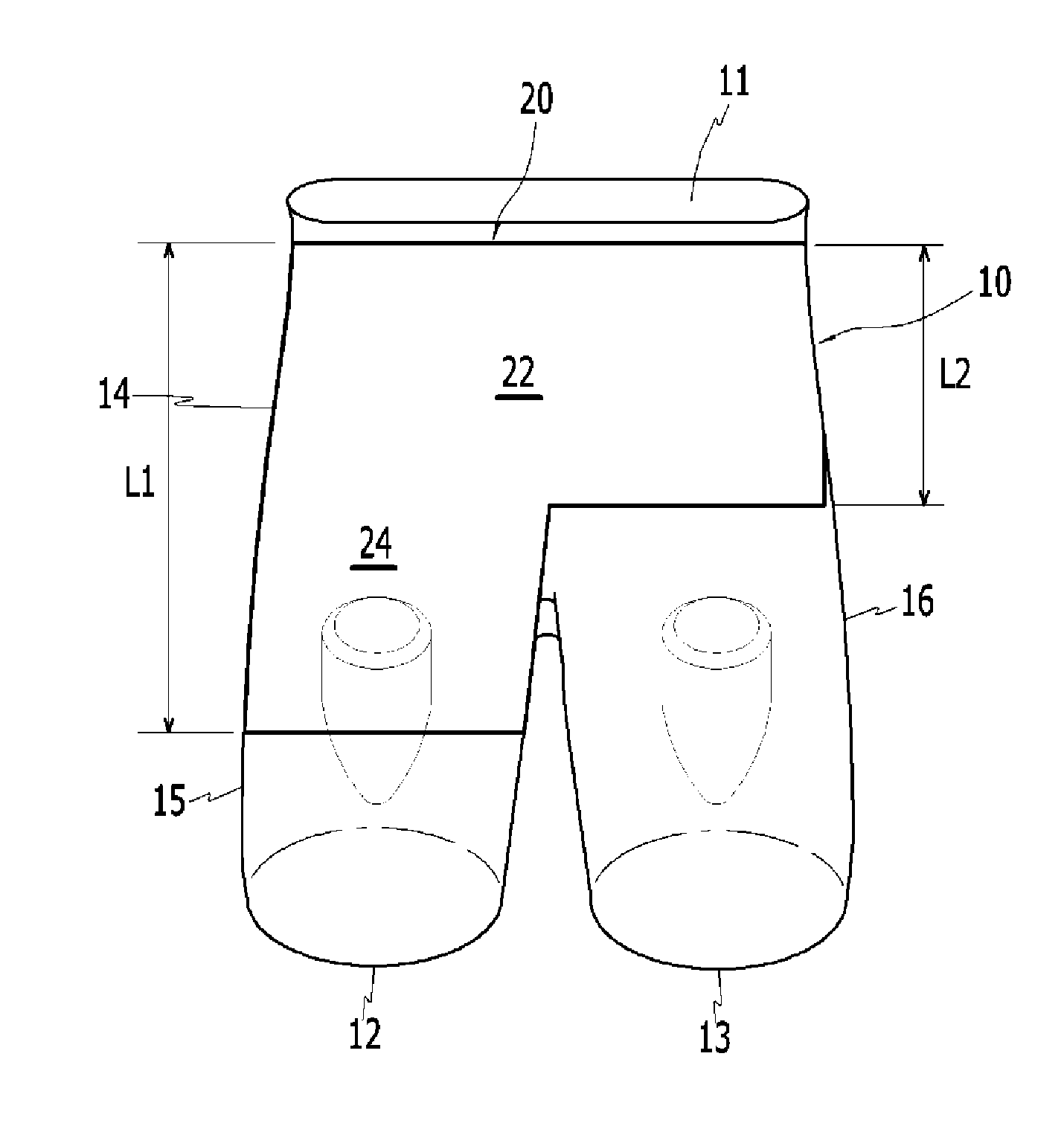
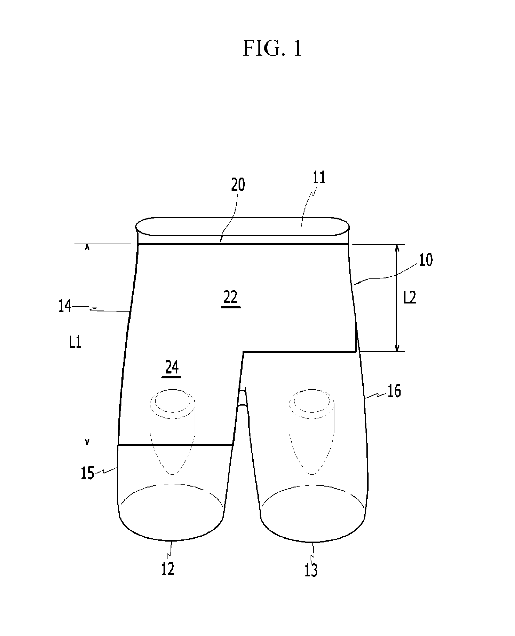
[0041]Referring to FIG. 1, a variable intake manifold 10 according to an exemplary embodiment of the present invention includes an inlet 11 for drawing outside air in and first and second outl...


PUM


Abstract

A variable intake manifold apparatus for an internal combustion engine, may include an inlet drawing in outside air and being connected to a main passage, first and second outlets branched from the main passage and fluid-connected to the inlet through the main passage and releasing the outside air drawn through the main passage through the first and second outlets, and a partition dividing the main passage and one of the first and second intake passages.

Description

CROSS-REFERENCE TO RELATED APPLICATION[0001]The present application claims priority to Korean Patent Application No. 10-2012-0147808 filed on Dec. 17, 2012, the entire contents of which is incorporated herein for all purposes by this reference.BACKGROUND OF THE INVENTION[0002]1. Field of the Invention[0003]The present invention relates to a variable intake manifold for an internal combustion engine and a variable air intake device using the same, and more particularly, to a variable intake manifold for an internal combustion engine and a variable air intake device, which enhance tumble and swirl flows of intake air.[0004]2. Description of Related Art[0005]In general, a combustion chamber is formed in an internal combustion engine for directly injecting fuel for combustion by coupling a cylinder head to a cylinder block, and a piston is configured to reciprocate in the cylinder block to compress or expand the combustion chamber and vary the volume of the combustion chamber.[0006]An i...

Claims


Application Information

Patent Timeline
IPC IPC(8): F02B31/04F02B31/06
CPCF02B31/06F02B31/04Y02T10/12F02M35/104F02B27/02
Inventor HAN, DONG HEEHAN, SEUNG KOOKLIM, HYUN JUNCHU, DONG HOKIM, YOON JOOKIM, JI HOIM, HYUKPARK, JONG IL
Owner HYUNDAI MOTOR CO LTD
Why Eureka
Try Eureka