Optically-powered sensor systems principally for deployment on-board aircraft

Active Publication Date: 2014-06-19
SAFRAN AEROTECHNICS
View PDF9 Cites 15 Cited by
  • Summary
  • Abstract
  • Description
  • Claims
  • Application Information

AI Technical Summary

Benefits of technology

[0008]The present invention provides optically-powered sensing systems supplying these advantageous features. An optical interface uses light to deliver energy in order to

Problems solved by technology

However, many require levels of optical radiation greater than appropriate for u

Method used


Image

  • Optically-powered sensor systems principally for deployment on-board aircraft
  • Optically-powered sensor systems principally for deployment on-board aircraft
  • Optically-powered sensor systems principally for deployment on-board aircraft

Examples


Example

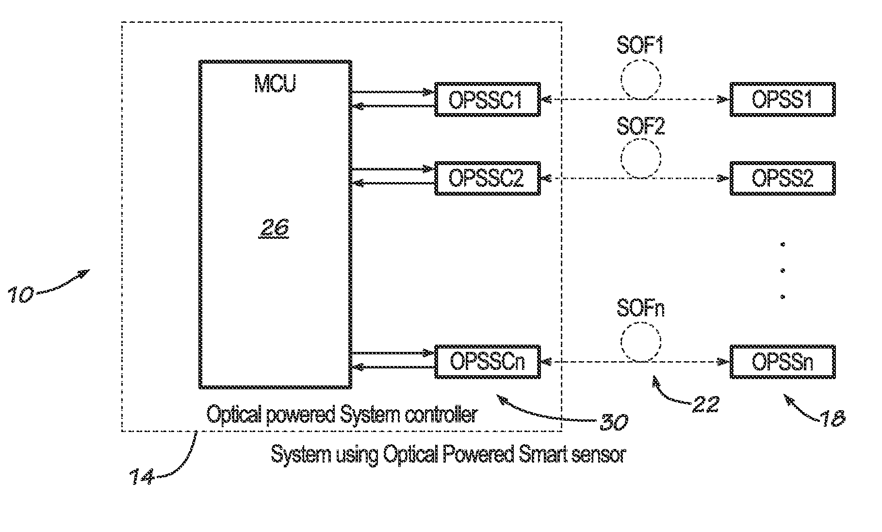
[0034]Illustrated in FIG. 1 is an exemplary sensing system 10 of the present invention. Included as part of system 10 may be system controller 14, one or more sensors 18, and one or more optical fibers 22. Optical fibers 22 function to transmit energy (power) and data between the sensors 18 and the system controller 14. The optical fibers 22 thus replace metal wires often used to transfer energy or information in the form of electricity.

[0035]As shown in FIG. 1, system controller 14 may include both microcontrol unit 26 and one or more sensor controls 30. In the preferred version of system 10 depicted in FIG. 1, a single optical fiber 22 couples each sensor 18 to a corresponding sensor control 30. While presently preferred, such 1:1 correspondence among fibers 22, sensors 18, and sensor controls 30 is not absolutely necessary, however.

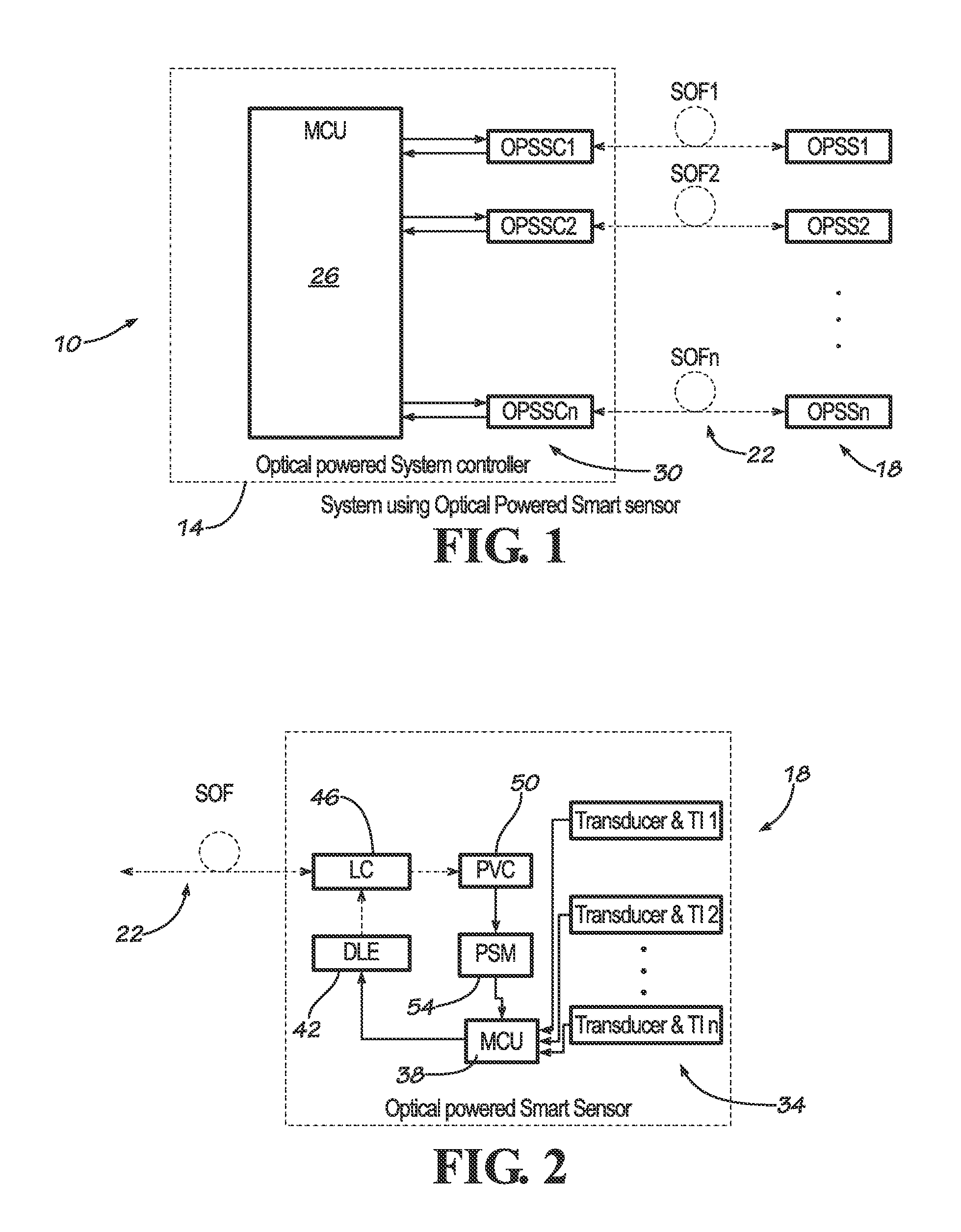
[0036]FIG. 2 shows a sensor 18 together with its corresponding optical fiber 22. Sensor 18 may comprise one or more transducers 34 (and associated int...


PUM


Abstract

Described are optical sensing systems. The systems may perform reliably in explosive environments and provide eye protection should breakage of an optical fiber be detected. Sensors of the systems additionally may be self-managing, acquiring and transmitting sensed data as available electrical power permits.

Description

CROSS-REFERENCE TO RELATED APPLICATION[0001]This application claims the benefit of U.S. Provisional Patent Application Ser. No. 61 / 739,168, filed Dec. 19, 2012, and entitled “System for Airborne Optical Powered Smart Sensors,” the entire contents of which application are incorporated herein by this reference.FIELD OF THE INVENTION[0002]This invention relates to sensing systems configured for reliable use in explosive (or other hazardous) environments and which provide eye protection should an optical fiber break. More particularly, the invention relates principally, but not necessarily exclusively, to systems in which free-running fuel sensors are powered optically on-board aircraft, with optical fibers both transmitting power to the sensors and receiving data signals from them.BACKGROUND OF THE INVENTION[0003]Various optically-powered sensor systems exist today. U.S. Pat. No. 4,820,916 to Patriquin discusses one such system, in which optical energy is transmitted along a bus for di...

Claims


Application Information

Patent Timeline
IPC IPC(8): G01J1/02
CPCG01D5/268G01J1/0228
Inventor HAUZERAY, SYLVAIN
Owner SAFRAN AEROTECHNICS
Why Eureka
Try Eureka