
Overlap patterns and image stitching for multiple-detector compressive-sensing camera

a compression sensing camera and overlap pattern technology, applied in image enhancement, television systems, instruments, etc., can solve the problems of large number of samples generated, overwhelming data volume, and limited frame rate attainable by the system

Inactive Publication Date: 2014-06-19
INVIEW TECH CORP
View PDF7 Cites 27 Cited by
  • Summary
  • Abstract
  • Description
  • Claims
  • Application Information

AI Technical Summary

Benefits of technology

The patent describes a method for reconstructing an image using a special light modulation device and an array of light sensing elements. A light pattern is created by the light modulation unit and each light sensing element captures a unique pattern. These patterns are then combined to create the complete image. This technique allows for the creation of high-quality images with improved depth of field and reduced blurring.

Problems solved by technology

A fundamental problem with any attempt to capture a signal x(t) according to Nyquist theory is the large number of samples that are generated, especially when B (or B−A) is large.
The same problem of overwhelming data volume is experienced when attempting to capture an image according to Nyquist theory.
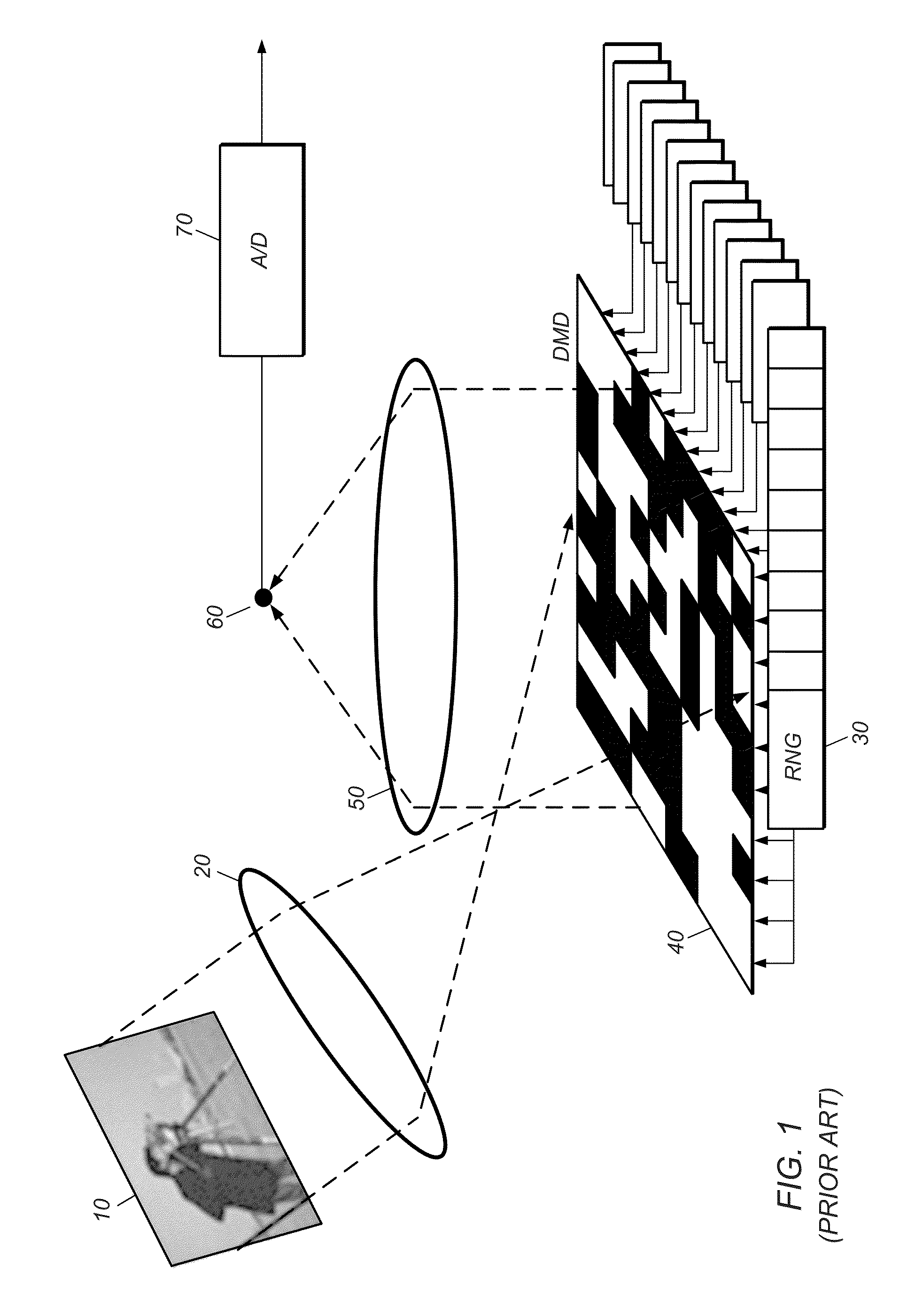
Because the DMD 40 applies the spatial patterns sequentially, and the pattern application rate of the DMD is limited, the frame rate attainable by the system is limited, even if it were endowed with an idealized processor capable of reconstructing each image instantaneously from its corresponding acquired sample set.
Although this parallel detector system is an improvement over the single-detector system, it has a difficulty associated with the so-called “crosstalk” (or “cross over”) of modulated light.
It is our observation that the prior art reconstruction method causes image reconstruction artifacts such as image noise and ghosting.

Method used


Image

  • Overlap patterns and image stitching for multiple-detector compressive-sensing camera
  • Overlap patterns and image stitching for multiple-detector compressive-sensing camera
  • Overlap patterns and image stitching for multiple-detector compressive-sensing camera

Examples


Embodiment Construction

[0053]Terminology

[0054]A memory medium is a non-transitory medium configured for the storage and retrieval of information. Examples of memory media include: various kinds of semiconductor-based memory such as RAM and ROM; various kinds of magnetic media such as magnetic disk, tape, strip and film; various kinds of optical media such as CD-ROM and DVD-ROM; various media based on the storage of electrical charge and / or any of a wide variety of other physical quantities; media fabricated using various lithographic techniques; etc. The term “memory medium” includes within its scope of meaning the possibility that a given memory medium might be a union of two or more memory media that reside at different locations, e.g., on different chips in a system or on different computers in a network.

[0055]A computer-readable memory medium may be configured so that it stores program instructions and / or data, where the program instructions, if executed by a computer system, cause the computer system...


PUM


Abstract

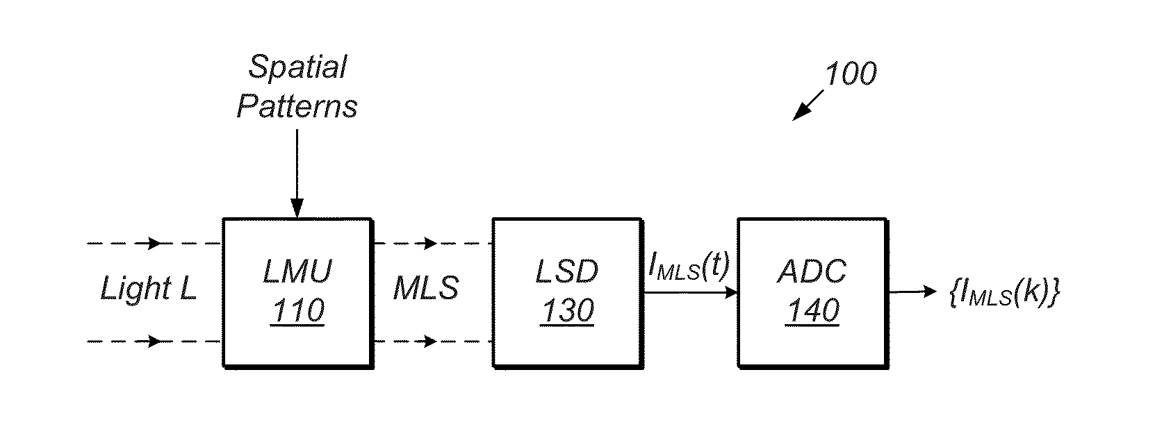
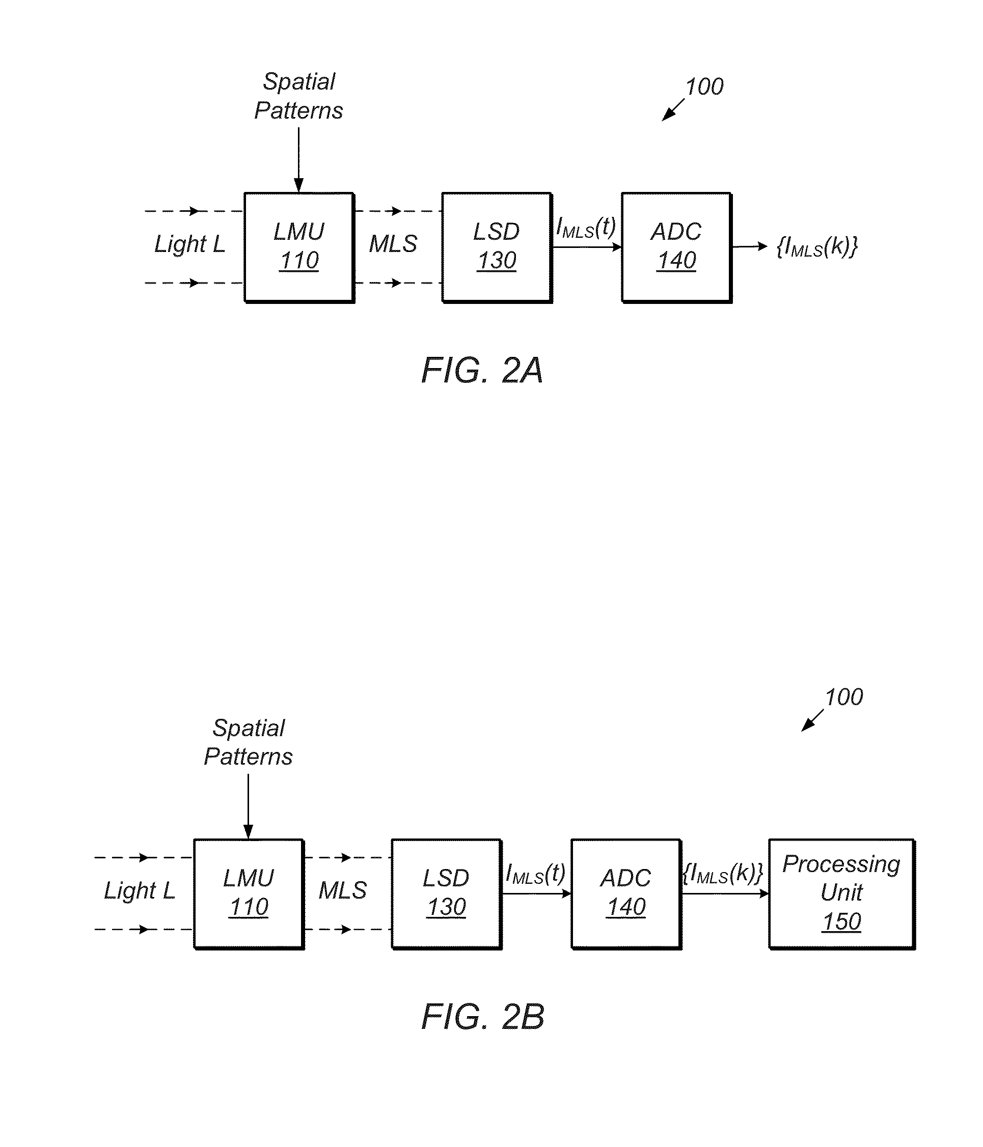
A mechanism for reconstructing sub-images based on measurement data acquired by an imaging system including an array of light modulating elements and an array of photodetectors. Each sub-image is reconstructed based on samples from a respective photodetector and a respective set of measurement patterns defined on a respective virtual sub-region on the modulating array. Each virtual sub-region is configured to include at least the light modulating elements that are able to send a non-trivial amount of light to the respective photodetector during a pattern application period. The virtual sub-regions overlap because many light modulating elements are capable of sending light to more than one photodetector. Whenever a measurement pattern of one virtual sub-region overlaps the measurement pattern of a neighboring virtual sub-region, the two measurement patterns agree by design. Thus, the measurement patterns for the collection of virtual sub-regions combine to form a pattern on the whole modulating array.

Description

RELATED APPLICATION DATA[0001]This application claims the benefit of priority to U.S. Provisional Application No. 61 / 737,401, filed on Dec. 14, 2012, entitled “Overlap Patterns and Image Stitching for Multiple-Diode CS Camera”, invented by Herman et al., which is hereby incorporated by reference in its entirety as though fully and completely set forth herein.GOVERNMENT LICENSE RIGHTS[0002]This invention was made with Government support under Contract No. 2009*0674524*000 awarded by the Central Intelligence Agency. The Government has certain rights in the invention.FIELD OF THE INVENTION[0003]The present invention relates to the field of compressive sensing, and more particularly, to a method for reconstructing images acquired using a light modulator and a parallel array of light detectors whose fields of view partially overlap.DESCRIPTION OF THE RELATED ART[0004]According to Nyquist theory, a signal x(t) whose signal energy is supported on the frequency interval [−B,B] may be recons...

Claims


Application Information

Patent Timeline
IPC IPC(8): G06T5/00
CPCG06T5/50G06T2207/10052G06T2207/20221G06T2207/20212G06T5/00
Inventor HERMAN, MATTHEW A.HEWITT, DONNA E.WESTON, TYLER H.MCMACKIN, LENORE
Owner INVIEW TECH CORP
Learn More