Light emitting apparatus

a technology of light-emitting apparatus and light-emitting cylinder, which is applied in the direction of instruments, static indicating devices, optics, etc., can solve the problems of increasing duty ratio, increasing rate, and lengthening the period of time for startup operation

Active Publication Date: 2014-06-19
ROHM CO LTD
View PDF5 Cites 35 Cited by
  • Summary
  • Abstract
  • Description
  • Claims
  • Application Information

AI Technical Summary

Benefits of technology

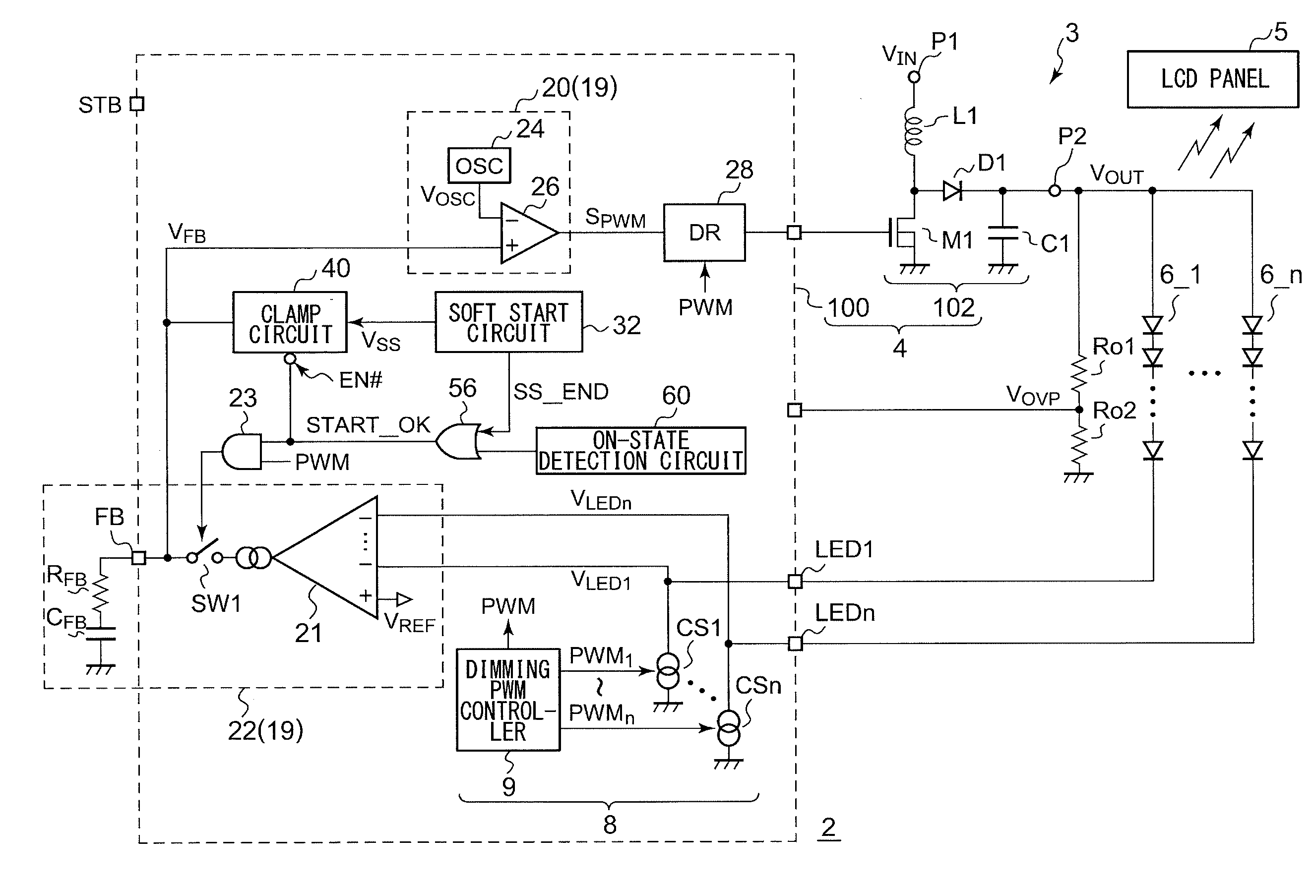
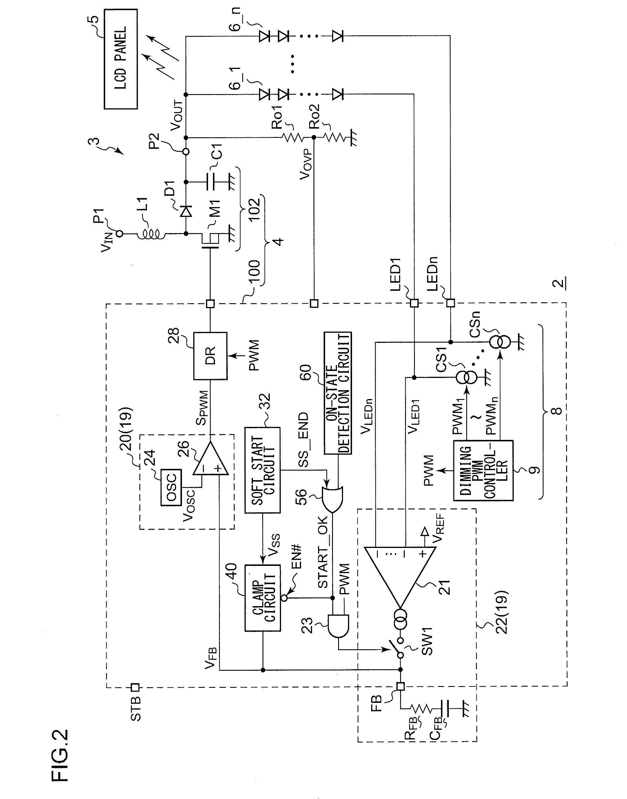
[0051]The voltage at the control electrode of the driving transistor falls as the driving current increases. Thus, by setting the threshold level to a su

Problems solved by technology

This leads to a reduction in the rising rate of the feedback voltage VFB, i.e., a reduction in the rising rate of the d

Method used


Image

  • Light emitting apparatus
  • Light emitting apparatus
  • Light emitting apparatus

Examples


Embodiment Construction

[0076]The invention will now be described based on preferred embodiments which do not intend to limit the scope of the present invention but exemplify the invention. All of the features and the combinations thereof described in the embodiment are not necessarily essential to the invention.

[0077]In the present specification, the state represented by the phrase the member A is connected to the member B″ includes a state in which the member A is indirectly connected to the member B via another member that does not substantially affect the electric connection therebetween, or that does not damage the functions or effects of the connection therebetween, in addition to a state in which the member A is physically and directly connected to the member B.

[0078]Similarly, the state represented by the phrase “the member C is provided between the member A and the member B” includes a state in which the member A is indirectly connected to the member C, or the member B is indirectly connected to t...


PUM


Abstract

A current driving circuit is connected to an LED terminal LEDi, and generates an intermittent driving current ILEDi that corresponds to a dimming pulse signal PWMi. An error amplifier generates a feedback voltage VFB that corresponds to the difference between a detection voltage VLEDi and a predetermined reference voltage VREF. A pulse modulator generates a pulse signal having a duty ratio that corresponds to the feedback voltage VFB. A fault detection comparator COMP_OPENi generates a fault detection signal OPEN_DET which is asserted when the detection voltage VLEDi is lower than a predetermined threshold voltage VOPEN<sub2>—</sub2>DET. A forced turn-off circuit instructs the current driving circuit to suspend the generation of the driving current ILEDi during a predetermined period after a switching power supply starts to operate. The fault detection circuit detects whether or not the fault detection signal OPEN_DETi has been asserted in a predetermined period.

Description

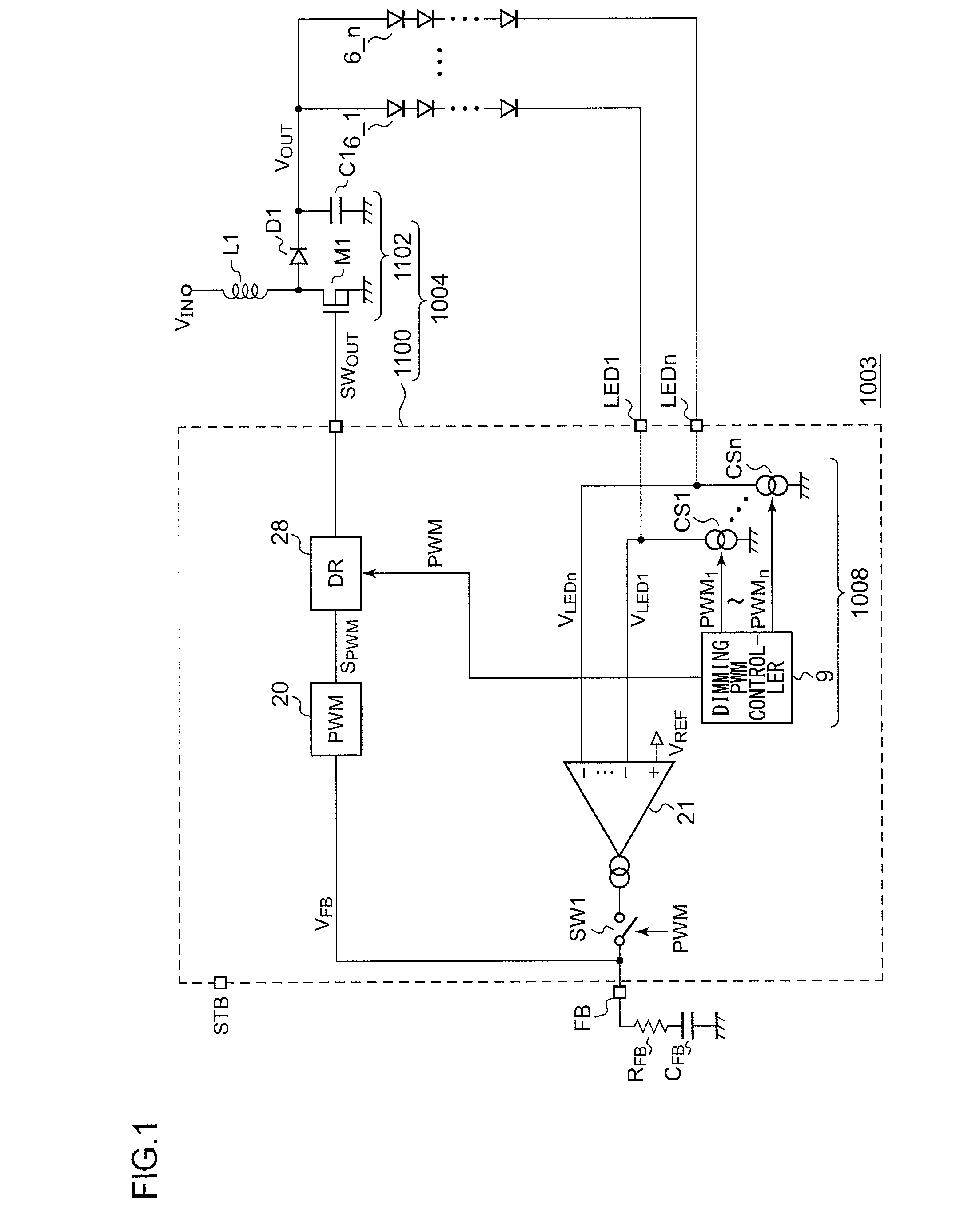
BACKGROUND OF THE INVENTION[0001]1. Field of the Invention[0002]The present invention relates to a light-emitting apparatus.[0003]2. Description of the Related Art[0004]In recent years, as a backlight of a liquid crystal panel or as an illumination device, a light-emitting apparatus is employed which uses a light-emitting element such as an LED (light-emitting diode) or the like. Related techniques are disclosed in Japanese Patent Application Laid Open No. 2006-114324, Japanese Patent Application Laid Open No. 2008-300208, Japanese Patent Application Laid Open No. 2006-339298, Japanese Patent Application Laid Open No. 2008-064477, Japanese Patent Application Laid Open No. 2008-258428, and Japanese Patent Application Laid Open No. 2007-158083. FIG. 1 is a circuit diagram showing an example configuration of a light-emitting apparatus investigated by the present inventor. It should be noted that the present applicant has recognized that the configuration and operation of a light-emitti...

Claims


Application Information

Patent Timeline
IPC IPC(8): G09G3/34H05B33/08H05B44/00
CPCH05B33/0815G09G3/3406H02M3/33507H05B45/14H05B45/347H05B45/38H05B45/382H05B45/39
Inventor KIKUCHI, HIROKIYONEMARU, MASAO
Owner ROHM CO LTD
Why Eureka
Try Eureka