Lens structure of a light emitting diode

a light-emitting diode and lens structure technology, applied in the field of optical lenses, can solve the problems of small lighting areas, affecting the effect of illumination of applied lighting equipment, and the difference of luminance between them is too large to achieve the effect of uniform illumination, and achieve the effect of improving the global illumination of lighting areas

Inactive Publication Date: 2014-06-19
LEDLINK OPTICS +2
View PDF4 Cites 20 Cited by
  • Summary
  • Abstract
  • Description
  • Claims
  • Application Information

AI Technical Summary

Benefits of technology

[0006]Therefore, the primary objective of the present invention is to provide a lens structure of a light emitting diode, adaptable for bac

Problems solved by technology

However, the divergence angle of the LED light is typically only about 120° resulting in smaller lighting areas compared with traditional light sources and affecting the effects of illumination of applied lighting equipment.
Additionally, the light sources from LEDs are mostly concentrated in the central part, such that the light sources from the central part has stronger i

Method used


Image

  • Lens structure of a light emitting diode
  • Lens structure of a light emitting diode
  • Lens structure of a light emitting diode

Examples


Embodiment Construction

[0021]The technical contents of the present invention will become apparent with the detailed description of preferred embodiments and the illustration of related drawings as follows.

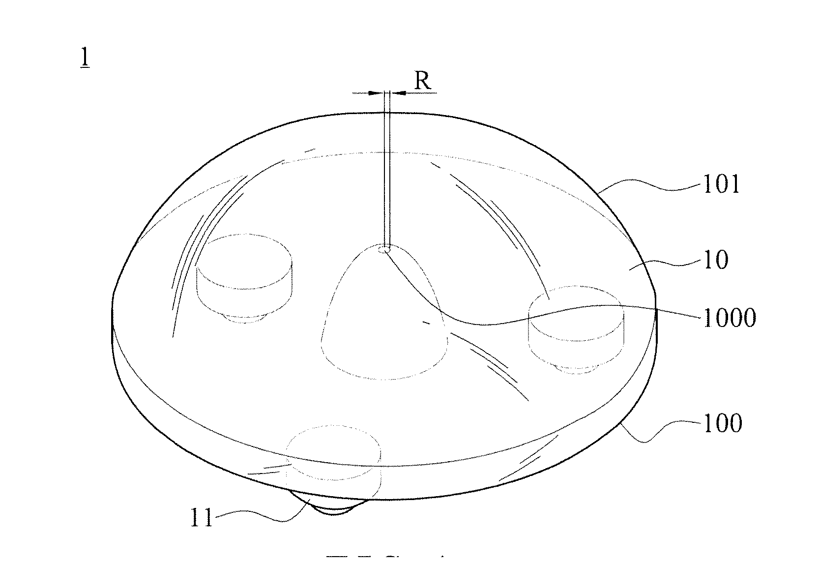
[0022]With reference to FIG. 1 for a perspective view of a first embodiment of a lens structure of light emitting diode in accordance with the present invention. Taking a backlight module of a display device as an example, as shown in FIG. 1, the lens of a light emitting diode 1 is used to combine with a light emitting diode (not shown) and then to be applied as a backlight source. The lens structure of the light emitting diode 1 has a body 10 and a least one convex 11. The body 10 has an outer surface formed by connection of an edge of a light input surface 100 and an edge of a light output surface 101. A recess is formed on the central part of the light input surface 100 toward the light output surface 101 for receiving the light emitting diode, and the recess can be formed convergently from an arc sur...


PUM


Abstract

A lens structure of a light emitting diode (LED) is provided, which includes a body. An outer surface of the body is formed by connection of an edge of a light input surface and an edge of a light output surface. A recess is formed convergently on the central part of the light input surface toward the light output surface. A divergent plane is formed on the end position of the recess. The divergent plane is a round surface with a radius of 0.05 mm to 1 mm. The divergence of the central light emitting from the LED is reinforced via the light output surface, and the amount of the central light emitting from the LED is limited by the area of the divergent plane. Accordingly, the difference of luminous intensity between the central part and the edge of the lighting area can be improved, thereby providing effects of uniform illumination.

Description

BACKGROUND OF THE INVENTION[0001]1. Field of the Invention[0002]The present invention relates to an optical lens, and more particularly to a lens structure of a light emitting diode (LED) that can change the original light emission angle, the distribution of luminous intensity and the distribution of illuminance using the theory of secondary optical refraction, to adjust the distribution of illuminance in the lighting area, and thus promote the adaptability of LEDs in the various fields of application.[0003]2. Description of the Related Art[0004]Light emitting diodes (LED) having characteristics of low power consumption, high efficiency and long lifetime are very popular in the whole market of illumination products. All of a sudden, LEDs are mainly in place of traditional light sources and used widely in lighting equipment, such as backlight modules of display devices, advertising billboards, streetlamps, patio lights or desk lamps. However, the divergence angle of the LED light is ...

Claims


Application Information

Patent Timeline
IPC IPC(8): F21V5/04
CPCF21V5/04F21W2131/103F21Y2115/10G02B19/0014G02B19/0061G02B27/0927G02B27/0955
Inventor TANG, TE-LUNGWEI, CHIH-MING
Owner LEDLINK OPTICS
Why Eureka
Try Eureka