Medical imaging system

a medical imaging and imaging system technology, applied in the field of medical imaging systems, can solve the problems of patient's joint cartilage, high-cost apparatus, difficult to capture x-ray absorption images, etc., and achieve the effect of accurately measuring the thickness or other quantitative features of joint cartilag

Active Publication Date: 2014-06-19
KONICA MINOLTA INC
View PDF4 Cites 25 Cited by
  • Summary
  • Abstract
  • Description
  • Claims
  • Application Information

AI Technical Summary

Benefits of technology

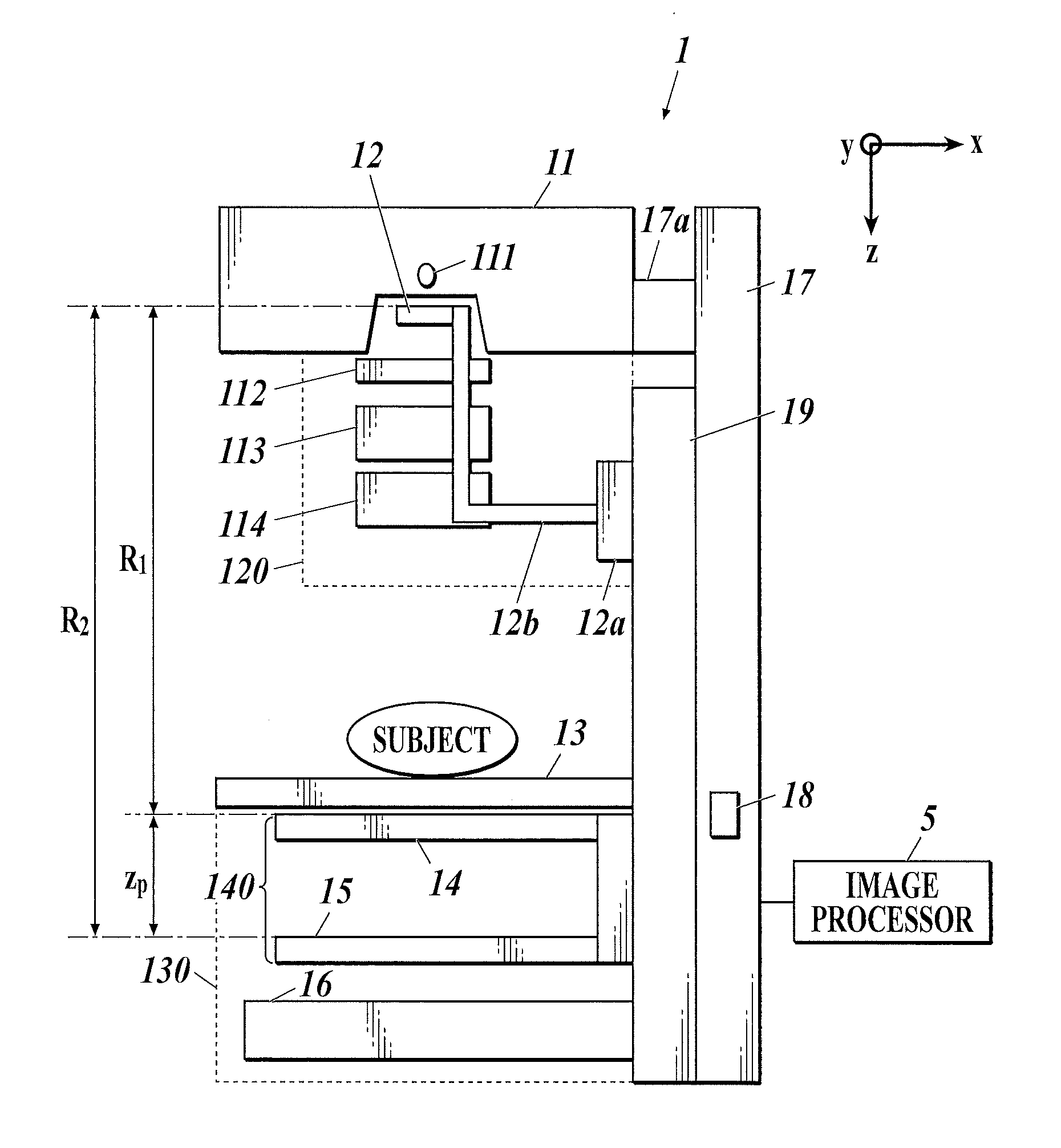
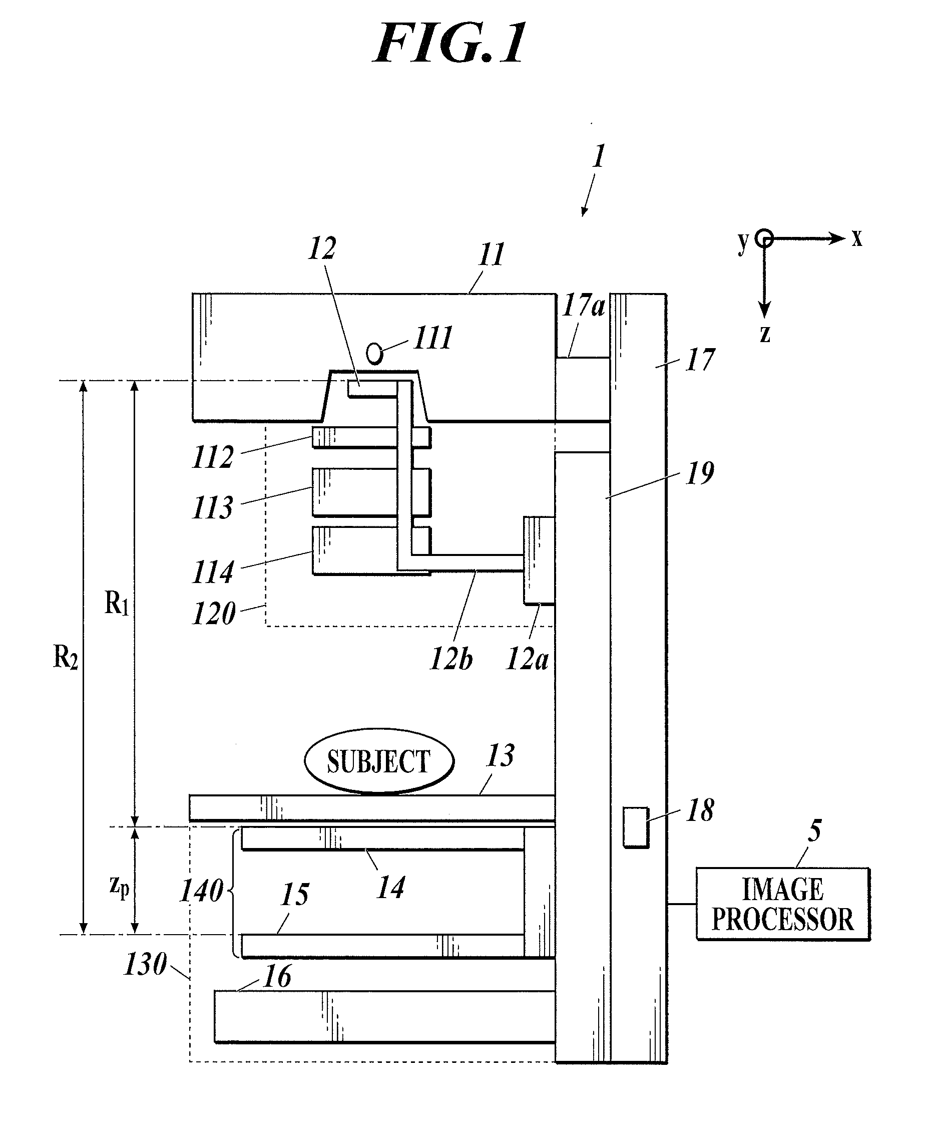
[0014]An object of the present invention, which has been made to solve such a problem, is to provide a medical imaging system that can accurately measure the thickness or other quantitative features of joint cartilage from, for example, a differential phase image of the cartilage reconstructed from a moire image captured by an X-ray imaging apparatus provided with a Talbot interferometer or Talbot-Lau interferometer.

Problems solved by technology

It is quite difficult to capture X-ray absorption images (i.e., common X-ray images captured with traditional silver halide films) of patient's joint cartilage.
Magnetic resonance imaging (MRI), which can image joint cartilage, requires a high-cost apparatus and has high running costs and thus has increased inspection costs.
Besides, MRI produces low resolution images that involve, for example, a risk of inaccurate measurement of the thickness of cartilage.
A doctor, who is not specialized in imaging diagnostic, cannot determine the features from such low resolution images and has no choice but to relay on the specialist's estimation.

Method used


Image

  • Medical imaging system
  • Medical imaging system
  • Medical imaging system

Examples


example 1

[0092]Examples of the quantitatively measured features of joint cartilage include the distance R (see FIG. 8) between the edge A of the detected cartilage and the edge B of the bone in the joint specified in the differential phase image as described above.

[0093]If the location at which the distance R is measured in the joint varies at every imaging, continuous monitoring of changes in distance R cannot be achieved, preventing the observation of the degree of abrasion and other abrasion states of cartilage. The location at which the distance R is measured can be kept at a given location in the joint in the following manner, for example.

[0094]As described above, if the cross section of the edge B of the bone in the joint does not have an arc-shaped edge, the joint cannot be bent smoothly. The cross section therefore partly has a substantially arc-shape edge in many cases. For this reason, a portion that can be relatively accurately approximated by an arc shape (the shaded portion in t...

modification 1

[Modification 1]

[0100]Although not shown in the drawing, the image processor 5 in Example 1 may include a display unit to display images, and input unit, such as a keyboard and a mouse, through which an operator, for example, a radiological technologist inputs instructions. The display unit shows a differential phase image, a line L, and the like. For instance, the distance R (i.e., the thickness) of cartilage on the line L input by the operator via the input unit may be calculated.

example 2

[0101]Instead of or in addition to the calculation of only one distance R of the cartilage in the area corresponding to the portion (i.e., distance R of the cartilage at the center of an arc-shaped portion, which is particularly prone to abrasion) as in Example 1, the process may calculate at least one of the maximum Rmax, the minimum Rmin, the difference ΔR between the maximum and the minimum, and the average Rave of the distance R at least in the area corresponding to a portion of the joint which can be approximated by an arc shape.

[0102]For instance, in FIG. 8, the line L is rotated about the center C within the range corresponding to the portion that can be approximated by an arc shape (the shaded portion in the drawing). While the line L is being rotated, the distance R (i.e., thickness) of the cartilage is calculated in the above-described manner. The maximum Rmax, the minimum Rmin, the difference ΔR between the maximum and the minimum, and / or the average Rave of the distance ...


PUM


Abstract

A medical imaging system includes an X-ray imaging apparatus and an image processor. The X-ray imaging apparatus is provided with a Talbot or Talbot-Lau interferometer and includes an X-ray source, an X-ray detector, and a subject table. The image processor generates a differential phase image, and optionally, one or both of an X-ray absorption image and a small-angle scattering image of the subject on the basis of the image signal of the subject. The image processor specifies a location of an edge of a bone in the joint on the basis of at least one of the generated images; and detects an edge of a cartilage in the joint in the differential phase image on the basis of the specified location of the bone edge to quantitatively measure a feature of the cartilage.

Description

BACKGROUND OF THE INVENTION[0001]1. Field of the Invention[0002]The present invention relates to a medical imaging system including an X-ray imaging apparatus provided with a Talbot interferometer or Talbot-Lau interferometer.[0003]2. Description of Related Art[0004]It is quite difficult to capture X-ray absorption images (i.e., common X-ray images captured with traditional silver halide films) of patient's joint cartilage.[0005]Magnetic resonance imaging (MRI), which can image joint cartilage, requires a high-cost apparatus and has high running costs and thus has increased inspection costs. Besides, MRI produces low resolution images that involve, for example, a risk of inaccurate measurement of the thickness of cartilage.[0006]With MRI, a doctor specialized in imaging diagnostic estimates the thickness or other features of cartilage from captured images, on the basis of knowledge or experience, in many cases. A doctor, who is not specialized in imaging diagnostic, cannot determine...

Claims


Application Information

Patent Timeline
Patent Type & Authority Applications(United States)
IPC IPC(8): A61B6/00
CPCA61B6/505A61B6/484A61B6/5217G06T7/0083G06T2207/10116G06T2207/30008G06T7/0012G06T2207/20136G06T7/12G06T7/181G16H50/30
Inventor HOSHINO, YOSHIHIDE
Owner KONICA MINOLTA INC
Why Eureka
Try Eureka