Dual-frequency coaxial earphone

a coaxial earphone and dual-frequency technology, applied in the direction of transducer details, earpiece/earphone attachment, electrical transducer, etc., can solve the problems of inadequacies in presenting voices and the size of conventional earphones for such modifications

Active Publication Date: 2014-06-19
JETVOX ACOUSTIC
View PDF2 Cites 31 Cited by
  • Summary
  • Abstract
  • Description
  • Claims
  • Application Information

AI Technical Summary

Benefits of technology

[0010]According to the disclosure, the balanced armature loudspeaker unit is securely assembled to the rear end of the moving coil loudspeaker unit, so that the balanced armature loudspeaker unit and the moving coil loudspeaker unit are formed integrally as a whole; or, the balanced armature loudspeaker unit is securely assembled in the acoustic transmitting hole of the moving coil loudspeaker unit, so that the balanced armature loudspeaker unit and the moving coil loudspeaker unit are formed integrally as a whole. Based on this, because the acoustic waves generated from the balanced armature loudspeaker unit are transmitted to the central vibrating portion of the moving coil loudspeaker unit directly or through the acoustic transmitting hole, the acoustic waves generated from the balanced armature loudspeaker unit and the acoustic waves generated from the moving coil loudspeaker unit have the same phase and are outputted simultaneously, and the different frequencies from the balanced armature loudspeaker unit and the moving coil loudspeaker unit can be separated, so that the intermodulation distortion issue between the high acoustic frequency and the low acoustic frequency can be efficiently improved while the size of the earphone is miniaturized.

Problems solved by technology

However, since the high frequency acoustic waves and the low frequency acoustic waves have different wavelengths and amplitudes, the characters of the two different acoustic waves cannot be distinguished by only one vibrating diaphragm A2, so that in a conventional earphone, the high frequency acoustic waves and the low frequency acoustic waves has intermodulation distortion drawbacks thereby the voices cannot be presented clearly.
Although some earphone manufacturers want to assemble the high frequency speaker and the low frequency speaker into the conventional earphone so as to output the high frequency acoustic waves and the low frequency acoustic waves individually, the size of the conventional earphone is not appropriate for such modification.

Method used


Image

  • Dual-frequency coaxial earphone
  • Dual-frequency coaxial earphone
  • Dual-frequency coaxial earphone

Examples


Embodiment Construction

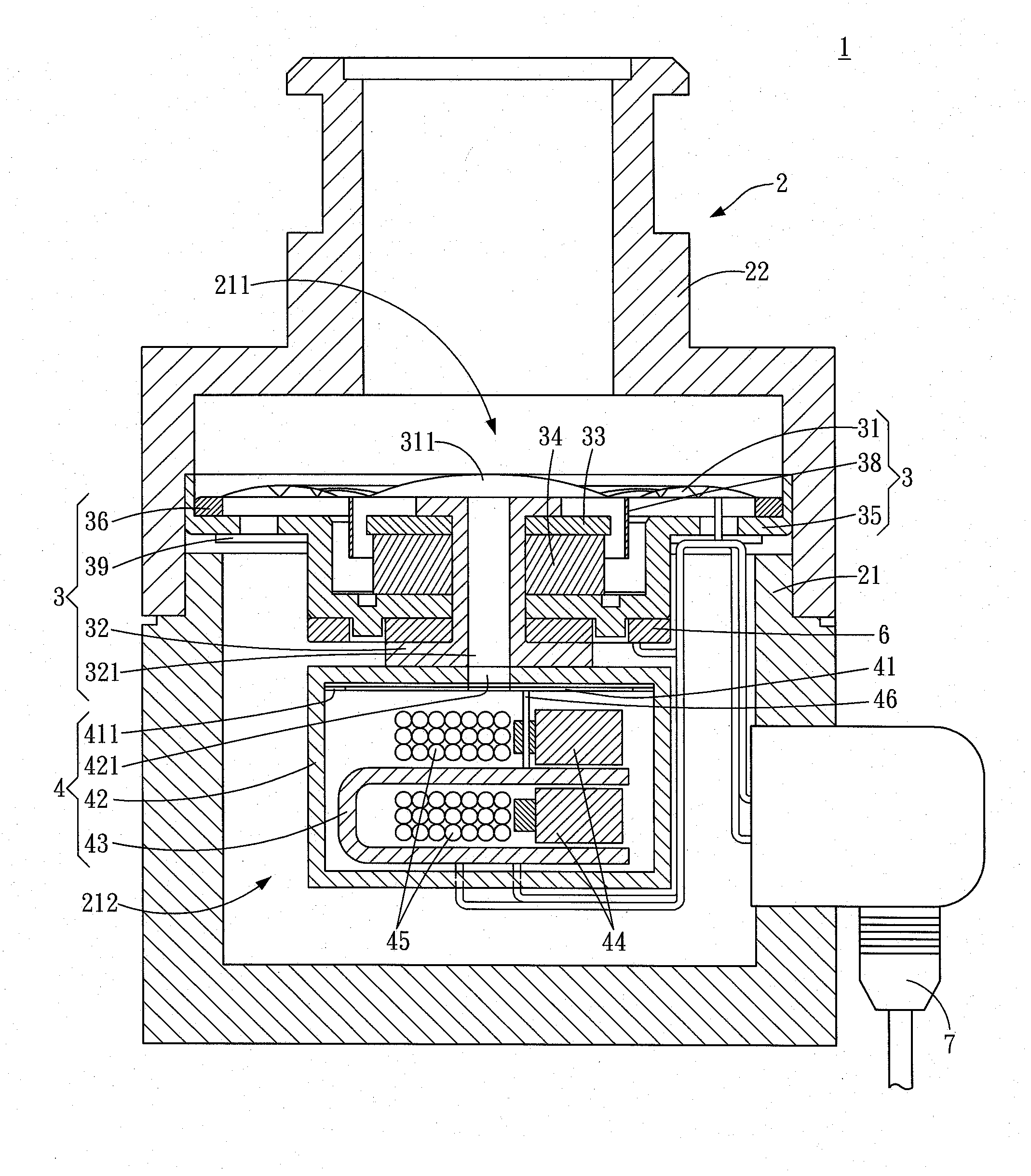
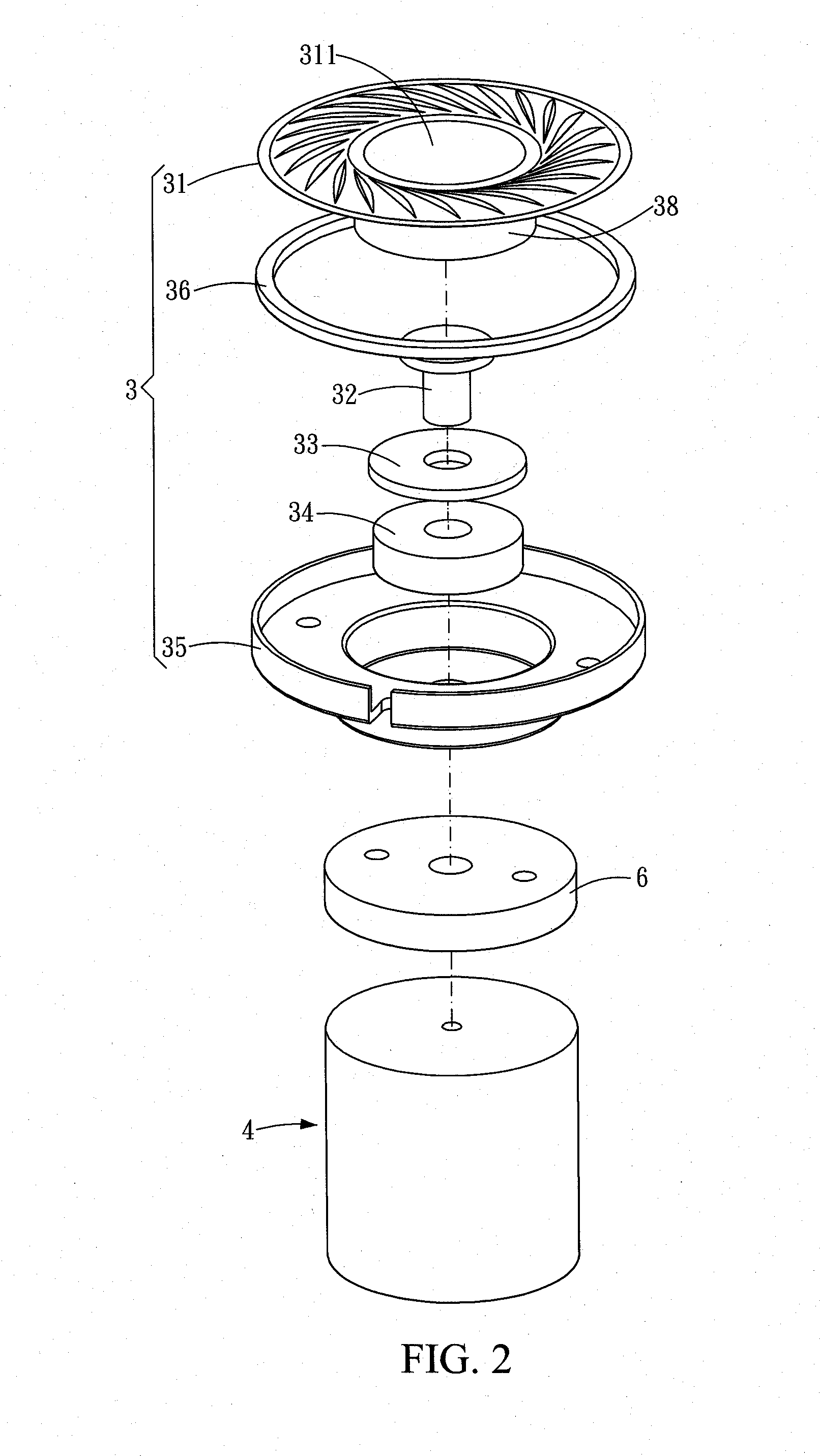
[0022]FIG. 2 and FIG. 3 show a first embodiment of a dual-frequency coaxial earphone of the disclosure. FIG. 2 is an exploded view of the first embodiment of the disclosure and FIG. 3 is a cross-sectional view of the first embodiment of the disclosure.

[0023]The dual-frequency coaxial earphone 1 in accordance with the first embodiment of the disclosure includes an earphone casing 2, a moving coil loudspeaker unit 3 and a balanced armature loudspeaker unit 4.

[0024]The earphone casing 2 is substantially consisting of a base 21 and a front cap 22. The base 21 has an acoustic output orifice 211. A receiving space 212 is defined in the base 21, and the receiving space 212 communicates with the acoustic output orifice 211. The front cap 22 is assembled at the acoustic output orifice 211.

[0025]The moving coil loudspeaker unit 3 is disposed in the receiving space 212 and has a moving coil vibrating diaphragm 31 and an acoustic transmitting member 32. The moving coil vibrating diaphragm 31 is...


PUM


Abstract

A dual-frequency coaxial earphone includes an earphone housing, a moving coil loudspeaker unit and a balanced armature loudspeaker unit. The earphone housing has a receiving space and an acoustic output orifice. The receiving space communicates with the acoustic output orifice. The moving coil loudspeaker unit is assembled in the receiving space and includes a moving coil vibrating diaphragm and an acoustic transmitting member. The moving coil vibrating diaphragm is assembled to face the acoustic output orifice and includes a central vibrating portion. The acoustic transmitting member includes an acoustic transmitting hole corresponding to the central vibrating portion. The balanced armature loudspeaker corresponds to the moving coil loudspeaker unit and includes an armature vibrating diaphragm. The armature vibrating diaphragm corresponds to the acoustic transmitting hole, so that the armature vibrating diaphragm and the moving coil vibrating diaphragm are respectively disposed at two ends of the acoustic transmitting member.

Description

CROSS-REFERENCES TO RELATED APPLICATIONS[0001]This non-provisional application claims priority under 35 U.S.C. §119(a) on Patent Application No. 101224176 and 101224673, filed in Taiwan, R.O.C. on 2012 Dec. 13 and 2012 Dec. 20, the entire contents of which are hereby incorporated by reference.BACKGROUND[0002]1. Technical Field[0003]The disclosure relates to an earphone structure, and particularly to a dual-frequency coaxial earphone.[0004]2. Related Art[0005]As shown in FIG. 1, a conventional earphone casing A10 has a signal cable A1, a vibrating diaphragm A2, a permanent magnet A3, a voice coil A4, a magnet conducting member A5 and a yoke A6 assembled therein. The voice coil A4 is assembled on the vibrating diaphragm A2 and encloses a periphery of the permanent magnet A3. A radial gap is defined between the voice coil A4 and the magnet conducting member A5. The permanent magnet A3 is sandwiched between the magnet conducting member A5 and the yoke A6.[0006]The signal cable A1 is con...

Claims


Application Information

Patent Timeline
Patent Type & Authority Applications(United States)
IPC IPC(8): H04R1/10
CPCH04R1/1058H04R1/24H04R9/06H04R11/02H04R1/1075H04R1/10
Inventor HUANG, YING-SHINHUANG, TO-TENG
Owner JETVOX ACOUSTIC
Why Eureka
Try Eureka