Outdoor-indoor MIMO communication system using multiple repeaters and leaky cables

a communication system and repeater technology, applied in repeater circuits, polarisation/directional diversity, site diversity, etc., can solve the problems of high bit-rate and spectral efficiency communication from outside base stations, difficult traffic load in wireless communication, and limited indoor coverage, so as to reduce the number of leaky cables. , the effect of halving the number of leaky cables

Active Publication Date: 2014-06-19
TELEFON AB LM ERICSSON (PUBL)
View PDF2 Cites 13 Cited by
  • Summary
  • Abstract
  • Description
  • Claims
  • Application Information

AI Technical Summary

Benefits of technology

[0013]The first and the second repeater in the wireless communication system may further share at least one leaky cable, and wherein said first repeater may feed said shared at least one leaky cable at one end and said second repeater may feed said shared at least one leaky cable at the other end. In this way the number of leaky cables can be halved.
[0014]The first repeater in the wireless communication system may further share at least one leaky cable with a second repeater and may share at least one other leaky cable with a third repeater, wherein said first repeater may feed said shared at least one leaky cable at one end

Problems solved by technology

A large part of today's traffic load in wireless communication comes from users inside physical structures such as office buildings, shopping malls, cafés and restaurants, etc.
Providing these indoor users with good coverage, high bit-rate and spectrally efficient communication from outside base stations is very challenging due to, for example, the penetration loss that occurs when the communication signals propagates through the walls of the building.
However the indoor coverage is typically limited to the close vicinity of the repeater donor ante

Method used


Image

  • Outdoor-indoor MIMO communication system using multiple repeaters and leaky cables
  • Outdoor-indoor MIMO communication system using multiple repeaters and leaky cables
  • Outdoor-indoor MIMO communication system using multiple repeaters and leaky cables

Examples


Embodiment Construction

[0033]Embodiments of the present invention will be described more fully hereinafter with reference to the accompanying drawings, in which embodiments of the invention are shown. This invention may, however, be embodied in many different forms and should not be construed as limited to the embodiments set forth herein. Rather, these embodiments are provided so that this disclosure will be thorough and complete, and will fully convey the scope of the invention to those skilled in the art. Like reference signs refer to like elements throughout the description.

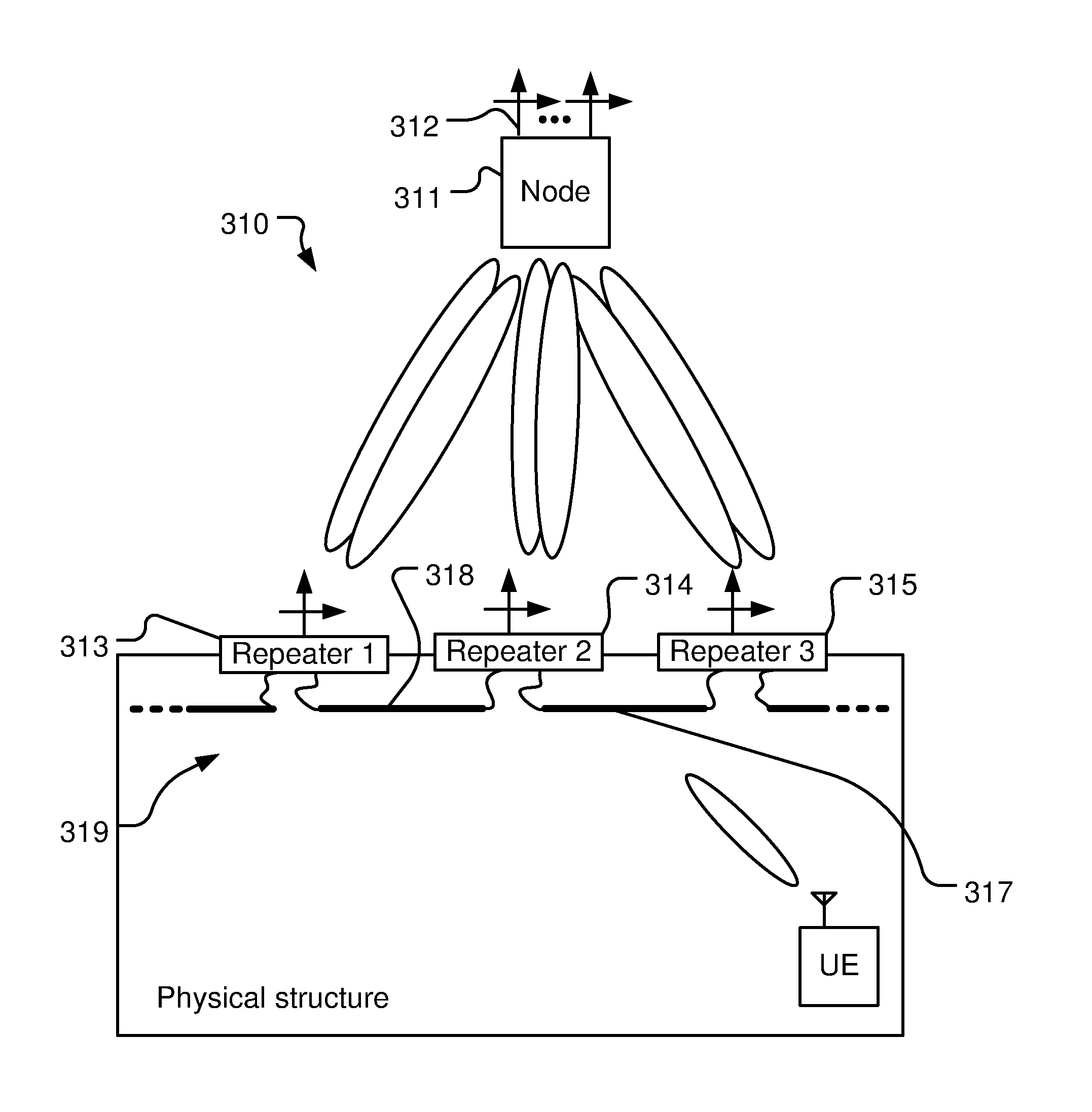
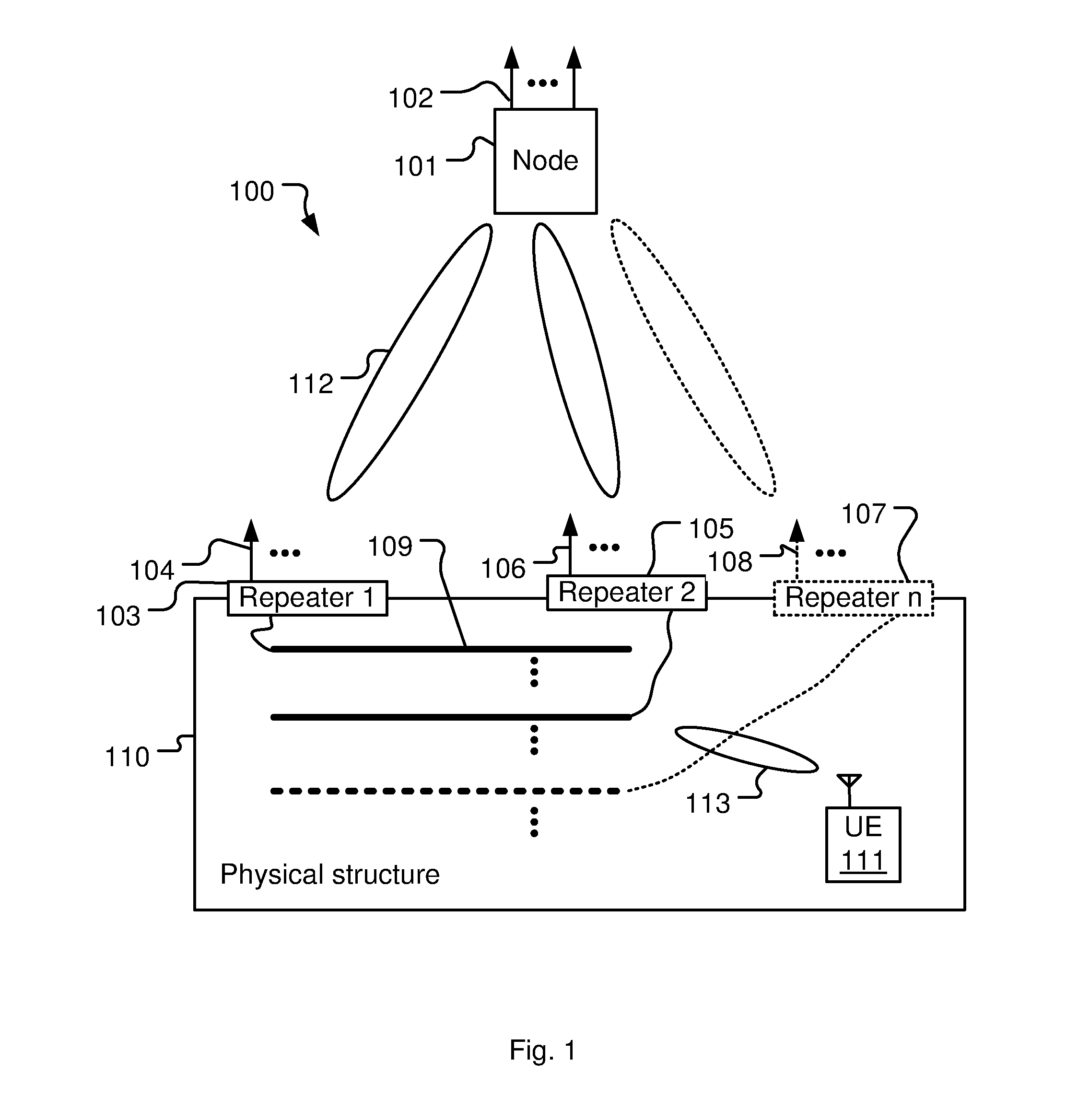
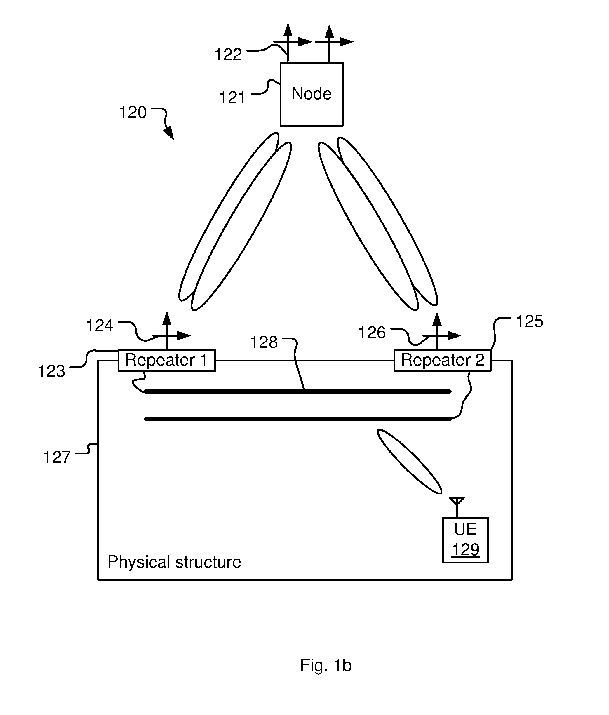
[0034]A way of offering good indoor coverage along with high bit-rate and spectrally efficient communication is to utilize a wireless outdoor-indoor MIMO communications system 100 according to an embodiment of the present invention. The wireless outdoor-indoor MIMO communications system 100, shown in FIG. 1, comprise of a node 101, and at least (as indicated by the dots in the figure) two node antennas 102, adapted for wireless MIM...


PUM


Abstract

The invention relates to a wireless outdoor-indoor multiple-input multiple-output (MIMO) communications system for communicating with user equipment located inside a physical structure such as a building. The MIMO communication system is comprised of a node having at least two node antennas, wherein the node is configured for line of sight (LOS) wireless MIMO communication with at least two outdoor-indoor repeaters, and of at least two outdoor-indoor repeaters adapted for LOS wireless MIMO communication with the node. The repeaters have at least one repeater antenna each, provided outside the physical structure, for LOS MIMO communication with the node and at least one leaky cable each, provided inside the physical structure, for indoor MIMO communication with the user equipment located inside the physical structure. The repeaters are provided outside on the same physical structure and spaced well-apart, and each leaky cable of each repeater is provided such that they provide the same indoor coverage of the same interior space in the physical structure.

Description

TECHNICAL FIELD[0001]The present invention relates to the field of wireless communication systems and, in particularly, to outdoor-indoor multiple-input multiple-output (MIMO) communication systems for communicating with user equipment located inside a physical structure such as a building.BACKGROUND[0002]A large part of today's traffic load in wireless communication comes from users inside physical structures such as office buildings, shopping malls, cafés and restaurants, etc. Providing these indoor users with good coverage, high bit-rate and spectrally efficient communication from outside base stations is very challenging due to, for example, the penetration loss that occurs when the communication signals propagates through the walls of the building.[0003]A well-known solution for enhancing communication signals inside a building is to use outdoor-indoor repeaters. An outdoor-indoor repeater has a pick-up antenna placed on the outside of the building connected via a double-direct...

Claims


Application Information

Patent Timeline
IPC IPC(8): H04B7/04H04B7/15
CPCH04B7/15H04B7/0486H04B5/0018H04B7/0413H04B7/10H04B7/2606H04W16/26H04B7/026H04B7/15514H04W88/02H04W88/08
Inventor NILSSON, ANDREASASPLUND, HENRIKCOLDREY, MIKAEL
Owner TELEFON AB LM ERICSSON (PUBL)
Why Eureka
Try Eureka