
Liquid crystal display device

a liquid crystal display and display device technology, applied in non-linear optics, instruments, optics, etc., can solve the problems of degrading the display quality of the liquid crystal display device, light leakage of the liquid crystal panel b>10/b>, etc., and achieves the effects of thin profile, narrow bezel, and light weigh

Active Publication Date: 2014-06-26
LG DISPLAY CO LTD
View PDF3 Cites 27 Cited by
  • Summary
  • Abstract
  • Description
  • Claims
  • Application Information

AI Technical Summary

Benefits of technology

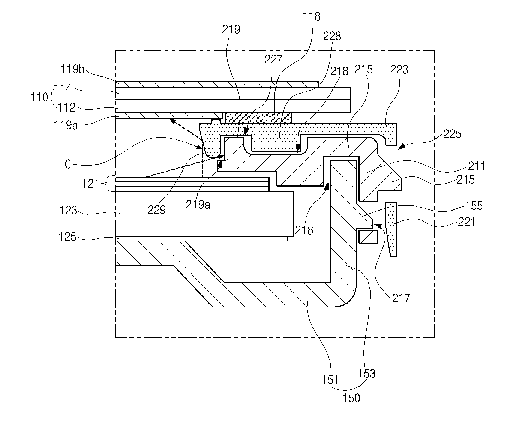
The present invention provides an LCD with the following technical effects: light weight, thin profile, narrow bezel, and prevention of deformation due to shrinkage and expansion of the liquid crystal panel. The invention includes a bottom cover with a horizontal surface and a side surface, a first guide panel, and a second guide panel. The first guide panel surrounds the peripheral portions of the backlight unit using a first vertical portion and includes a first horizontal portion that protrudes perpendicularly towards the inner side of the first vertical portion. The second guide panel includes a second vertical portion placed right on the outer side surface of the first guide panel and assembled and coupled to the outer side surface, and a second horizontal portion which protrudes perpendicularly towards the inner side of the second vertical portion and has a top surface onto which the liquid crystal panel is attached and fixed. A rib protrudes perpendicularly to the first horizontal portion at the top surface of the first horizontal portion, and a rib groove, into which the rib is inserted, is formed at the bottom surface of the second horizontal portion.

Problems solved by technology

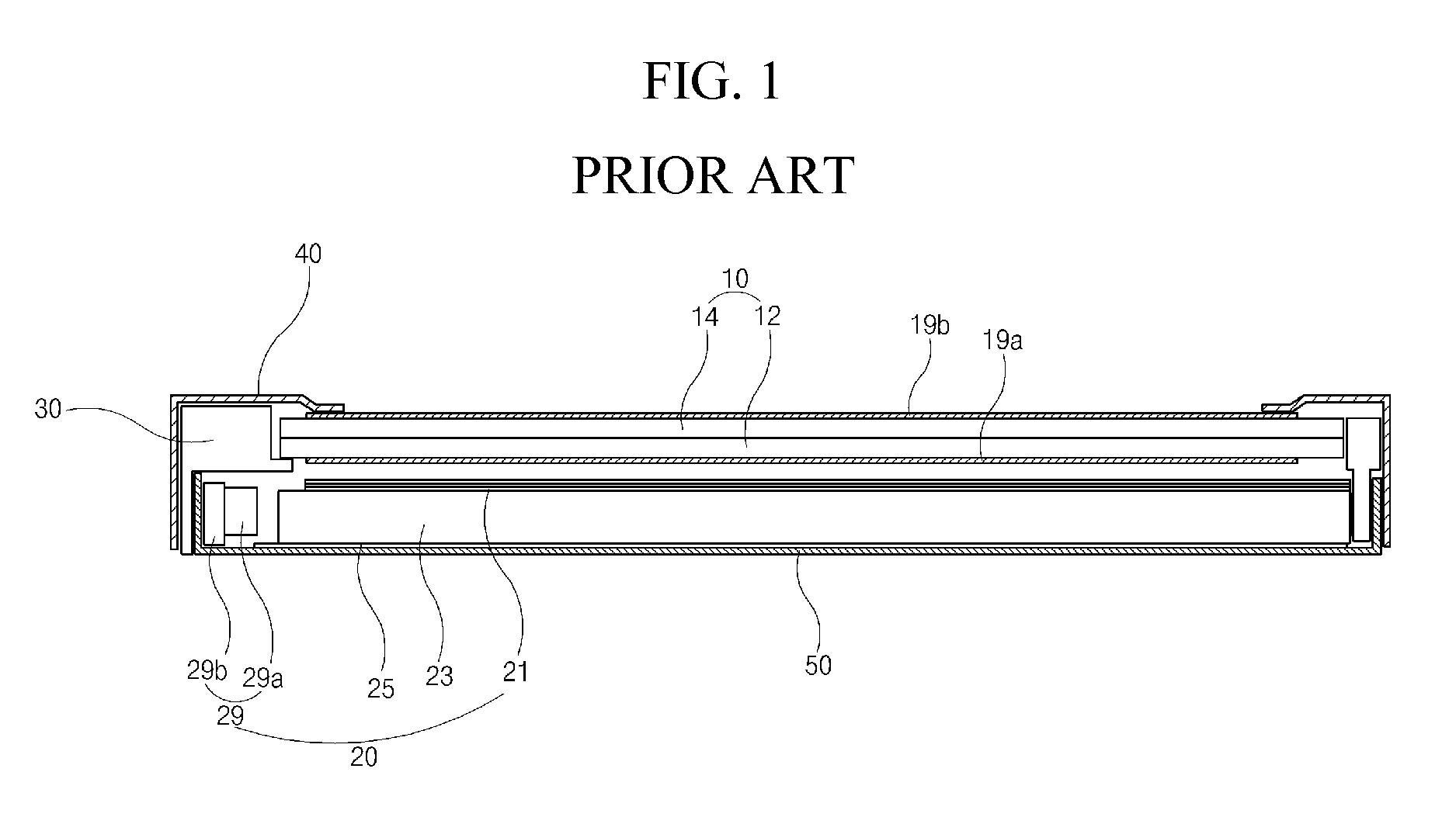
However, when this phenomenon occurs, since the liquid crystal panel 10 is attached to and fixed to the guide panel 30 using the adhesive pad, deformation due to shrinkage and expansion causes the liquid crystal panel 10 to be warped, and thus light leakage of the liquid crystal panel 10 occurs.
Therefore, display quality of the LCD is degraded.

Method used


Image

  • Liquid crystal display device
  • Liquid crystal display device
  • Liquid crystal display device

Examples


Embodiment Construction

[0035]Reference will now be made in detail to the illustrated embodiments of the present invention, which are illustrated in the accompanying drawings.

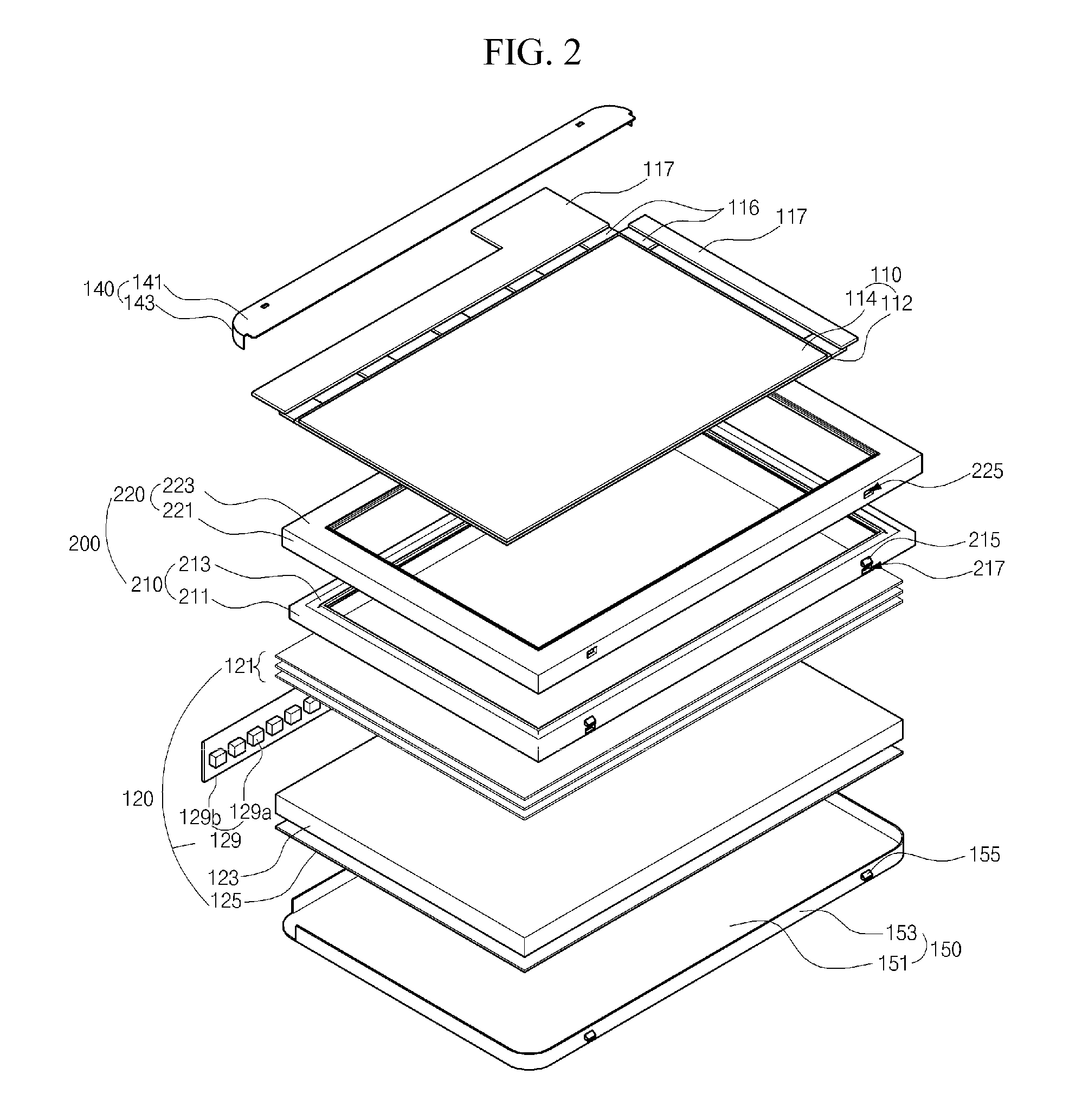
[0036]FIG. 2 is an exploded perspective view illustrating an LCD according to an embodiment of the present invention.

[0037]Referring to FIG. 2, the LCD includes a liquid crystal panel 110, a backlight unit 120, and mechanical components combining the liquid crystal panel 110 and the backlight unit 120, and the mechanical components includes a case top 140, a guide panel 200 of dual structure and a bottom cover 150.

[0038]Assuming that a display surface of the liquid crystal panel 110 faces the front, the backlight unit 120 is located at a back side of the liquid crystal panel 110. In a state that the liquid crystal panel 110 and the backlight unit 120 is surrounded by the guide panel 200 of double structure, the liquid crystal panel 110 and the backlight unit 120 are coupled with the case top 140 surrounding front edges of the liquid c...


PUM

PropertyMeasurementUnit
round shapeaaaaaaaaaa
thicknessaaaaaaaaaa
weightaaaaaaaaaa

Abstract

A liquid crystal display device includes a bottom cover including a horizontal surface, and a side surface; a first guide panel coupled with the bottom cover, surrounding peripheral portions of a backlight unit using a first vertical portion, and including a first horizontal portion protruding perpendicularly toward an inner side of the first vertical portion; and a second guide panel including a second vertical portion placed right on an outer side surface of the first vertical portion, and a second horizontal portion protruding perpendicularly toward an inner side of the second vertical portion and onto a top surface of which the liquid crystal panel is fixed, wherein a rib protrudes at a top surface of the first horizontal portion, and a rib groove, into which the rib is inserted, is formed at a bottom surface of the second horizontal portion.

Description

CROSS REFERENCE TO RELATED APPLICATIONS[0001]The present application claims the benefit of Korean Patent Application No. 10-2012-0152246, filed in Korea on Dec. 24, 2012, which is hereby incorporated by reference for all purposes as if fully set forth herein.BACKGROUND OF THE INVENTION[0002]1. Field of the Invention[0003]The present invention relates to a liquid crystal display device, and more particularly, to a liquid crystal display device having light weight, thin profile and narrow bezel.[0004]2. Discussion of the Prior Art[0005]A liquid crystal display device (LCD) is advantageous in displaying moving images and has high contrast ratio, and is widely used for TV, monitor or the like. The LCD displays images using optical anisotropy and polarization property of liquid crystal.[0006]The LCD includes a liquid crystal panel having two substrates and a liquid crystal layer therebetween, and alignment direction of liquid crystal is changed by an electric field to make difference of ...

Claims


Application Information

Patent Timeline
Patent Type & Authority Applications(United States)
IPC IPC(8): G02F1/1333
CPCG02F1/133308G02F2201/465G02F2201/54G02F1/133317G02F1/1333
Inventor HA, SEONG-HAE
Owner LG DISPLAY CO LTD
Learn More