Connector for LED module board

a technology of led module board and connector, which is applied in the direction of semiconductor devices for light sources, coupling device connections, lighting and heating apparatus, etc., can solve the problems of easy leakage and troublesome assembly work, and achieve excellent electrical connection stability, high thermal conductivity, and assembly excellent

Inactive Publication Date: 2014-06-26
SMK CORP
View PDF5 Cites 21 Cited by
  • Summary
  • Abstract
  • Description
  • Claims
  • Application Information

AI Technical Summary

Benefits of technology

[0017]Since a connector according to the present invention allows sub-assembly of an LED module board with a lower cover member and an upper cover member in advance, the LED module board can be attached to a heat sink in a state in which the LED module board is held by the connector, which is excellent in assembly.
[0018]Furthermore, since a connection terminal for power supply is brought into contact with a power supply pad of the LED module by a predetermined contact force when the lower cover member and the upper cover member are engaged with each other, the connector is excellent in stability of electrical connection.
[0019]Since the lower cover member has high thermal conductivity and insulation, the spatial creepage distance can be made longer by the lower cover member than that in the case of the related art where an LED module board is directly attached to a heat sink.

Problems solved by technology

With such a method for mounting an LED module board, however, the LED module board and the cover member that is a connector needs to be attached individually with the heat sink, which makes the assembly work troublesome.
Furthermore, as shown in FIG. 10(c), there is a problem that the contact force of a connection terminal 116a for power supply to a power supply pad provided on the LED module board varies with the tightening force of the fastening members 4a, 4b and is thus unstable.
As shown in FIG. 10(d), there is further a problem that the spatial creepage distance L0 from a contact of the connection terminal 116a to the heat sink 3 is short, which results in easy leakage.

Method used


Image

  • Connector for LED module board
  • Connector for LED module board
  • Connector for LED module board

Examples


first embodiment

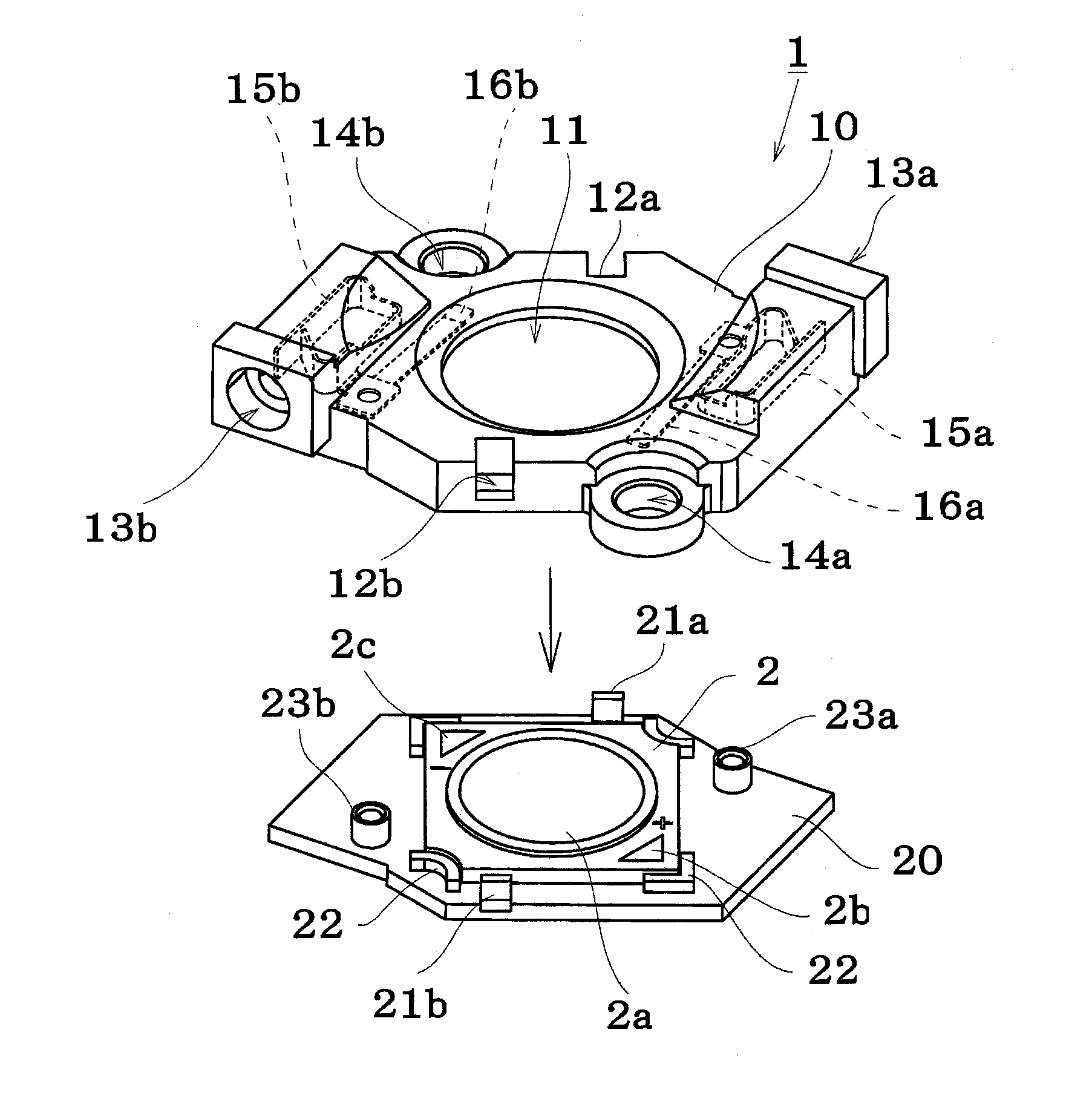
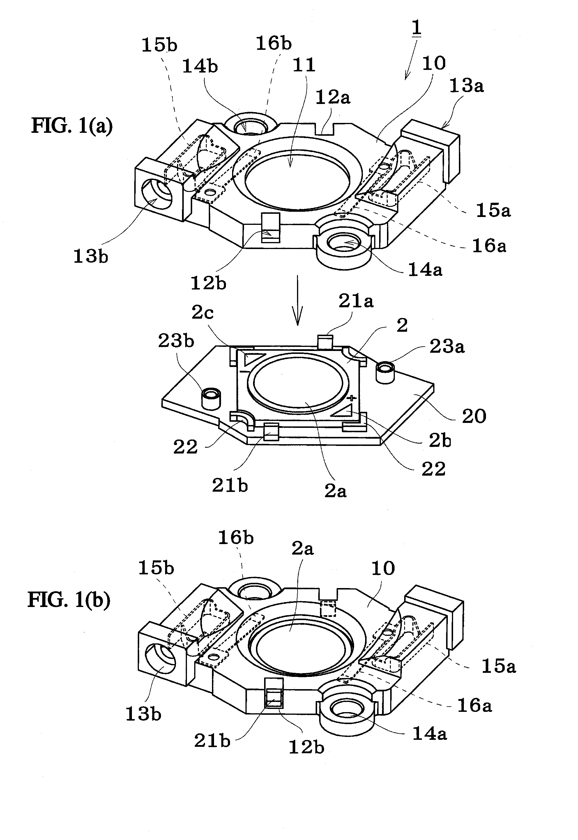
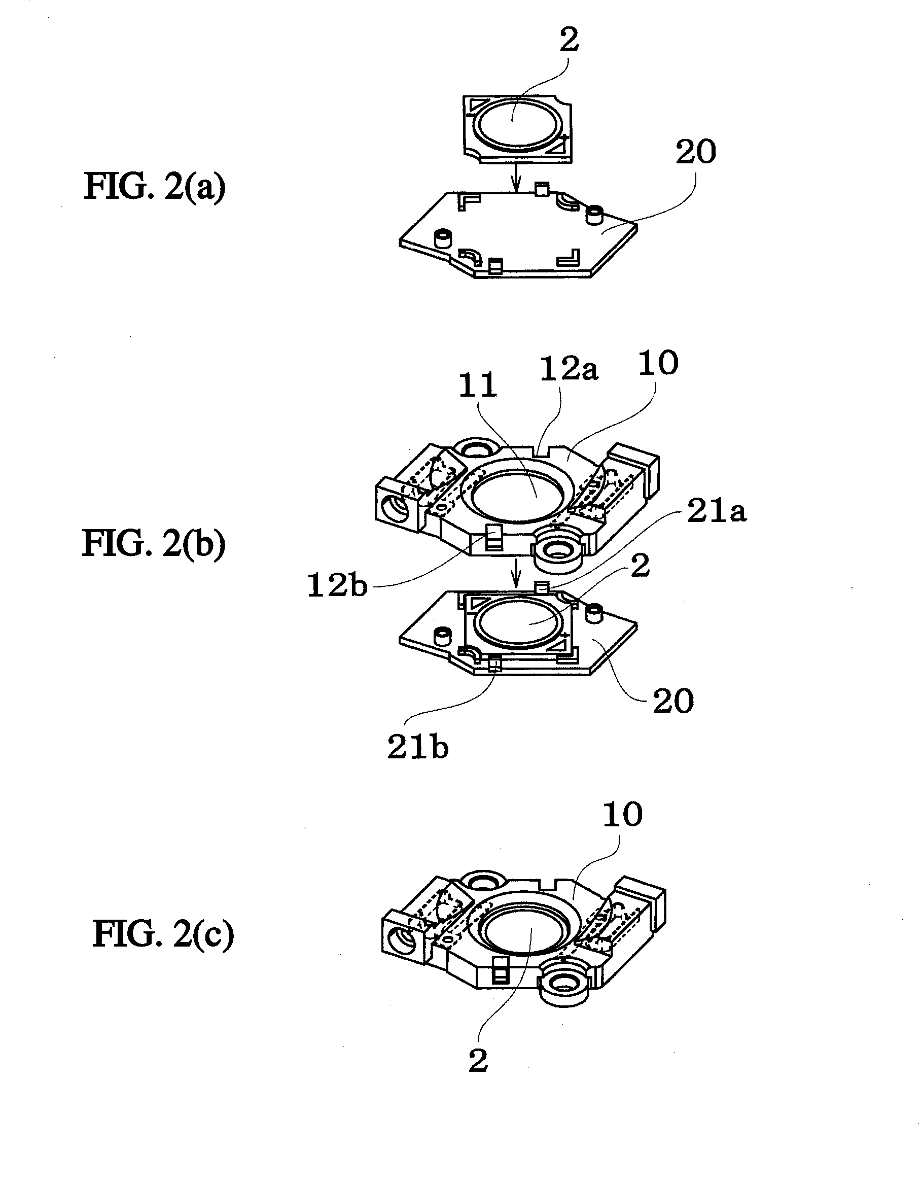
[0038]FIGS. 1(a) and 1(b) show the present disclosure, and FIGS. 2(a) to 2(c) show exemplary procedures for assembly.

[0039]A lower cover member 20 is formed of a thermally conductive and insulating resin material with a thermal conductivity (by steady state method) of 1.5 W / mK or higher, or preferably 5.0 W / mK or higher, and a dielectric breakdown voltage of 1 KV or higher as a raw material.

[0040]The lower cover member 20 has an upper face (a face on which the LED module board is placed) with a flat central part so that the rear face of the LED module board 2 is brought into close contact therewith.

[0041]The lower cover member 20 also has positioning members 22 such as projections and ribs where necessary so that the LED module board 2 can be easily positioned at a predetermined position when the LED module board 2 is placed on the lower cover member 20.

[0042]The lower cover member 20 is provided with claw-like locking portions 21a, 21b for engaging an upper cover member 10 as will ...

second embodiment

[0060]FIGS. 6(a), 6(b), and 7(a) to 7(e) show the present disclosure.

[0061]In the present embodiment, an opening 24 for allowing the LED module board 2 to be inserted into a lower cover member 20a is formed and a thermally-conductive insulating sheet 30 is provided to seal the opening as shown in FIG. 7(a).

[0062]A stepped portion 24a is formed at the inner circumference of the opening 24 so as to facilitate arrangement of the sheet.

[0063]In addition, a stepped portion 2d to be fitted thereto is formed in the rear face of the LED module board 2.

[0064]When the LED module board 2 is placed on the lower cover member 20a having such a structure, the upper cover member 10 and the lower cover member 20 are sub-assembled in such a manner that the rear face of the LED module board 2 is brought into close contact with the thermally-conductive insulating sheet 30 as shown in FIGS. 7(b) and 7(c).

[0065]FIG. 7(e) shows a state in which the connector is attached to the heat sink 3, which is an ass...


PUM


Abstract

There is provided a connector for an LED module board excellent in assembly, heat dissipation and insulation. The connector for an LED module board for holding and electrically connecting the LED module board includes: a lower cover member on which the LED module board is placed; and an upper cover member having a connection terminal brought into elastic contact with a power supply pad included in the LED module board, wherein at least a portion of the lower cover member at a position of a bottom face of the LED module board is made of a thermally-conductive and insulating material, the upper cover member is structured so that light emitted from the LED module board is directed outward, and the upper cover member is engaged with the lower cover member in a state in which the LED module board is placed on the lower cover member.

Description

CROSS-REFERENCE TO RELATED APPLICATIONS[0001]This application claims priority under 35 USC §119(a) to Japanese Patent Application No. JP 2012-282309, filed on Dec. 26, 2012, the entire contents of which is incorporated herein by reference.BACKGROUND[0002]1. Technical Field[0003]The present invention relates to a connector used for electrical connection of chip-on-board LED modules.[0004]2. Description of the Related Art[0005]Chip-on-board (COB) LED modules are boards on which LED devices are mounted to and have been employed in the field of lighting and the like. COB LED modules need to dissipate heat generated by LED devices (e.g., to its surrounding environment).[0006]Accordingly, in the related art and referring to FIG. 10A-10D collectively, an LED module board 2 is placed on a heat sink 3 for heat dissipation. A cover member 110 having a connection terminal for power supply is fixed onto the LED module board 2 and the heat sink 3 by fastening members 4a, 4b such as screws in a m...

Claims


Application Information

Patent Timeline
Patent Type & Authority Applications(United States)
IPC IPC(8): H01R13/717
CPCF21V29/20F21V19/003H01L24/72H01R13/2442F21Y2101/02F21Y2115/10F21V29/15F21V29/70F21V29/85H01R12/51H01L33/00H01R33/05
Inventor TANAKA, KATSUYOSHITAKEDA, TOSHIMITSU
Owner SMK CORP
Why Eureka
Try Eureka