
Method and a system for determining the geometry and/or the localization of an object

a technology of geometry and localization, applied in the field of method and system for determining the geometry and/or the localization of an object, can solve the problems of large matrix of shifted impulse response, high computational cost, and inapplicability of proposed algorithm in practice, and achieve the effect of multiple microphones

Inactive Publication Date: 2014-06-26
ECOLE POLYTECHNIQUE FEDERALE DE LAUSANNE (EPFL)
View PDF10 Cites 28 Cited by
  • Summary
  • Abstract
  • Description
  • Claims
  • Application Information

AI Technical Summary

Benefits of technology

The patent describes a method that can be used for a variety of signals, such as acoustic, radio, and UWB signals. The method can easily be extended to multiple sources and microphones. One embodiment involves a room with a loudspeaker and three microphones placed in a 2D geometry. The method allows for accurate determination of the room's 2D geometry using a reduced number of receivers.

Problems solved by technology

However the described algorithm does not propose to find the source location immediately as there is a huge number of intermediated steps and hypothesis.
Moreover since many impulse responses have to be measured by putting a fake wall at different positions with respect to the microphone array and the loudspeaker, the resulting matrix of shifted impulse responses is also quite huge and then computing expensive.
The described algorithm is based on the complete knowledge of first and second generation echo Times of Arrivals (TOAs): however the second generation is often difficult to obtain for practical reasons (e.g. attenuation of the signal).
Then the proposed algorithm is not applicable in practice since without using second-order echoes a single RIR does not suffice for reconstructing the shape of the room.
The known solutions are then not often applicable in practice.
They require also a huge number of receivers and / or transmitters.

Method used


Image

  • Method and a system for determining the geometry and/or the localization of an object
  • Method and a system for determining the geometry and/or the localization of an object
  • Method and a system for determining the geometry and/or the localization of an object

Examples


Embodiment Construction

[0067]The present invention will be now described in more detail in connection with its embodiment for determining the geometry of a room. However the present invention finds applicability of connection with many other fields, as will be discussed. Moreover the two-dimensional case will be described first for the sake of simplicity and illustrations. The three dimensional case then follows easily.

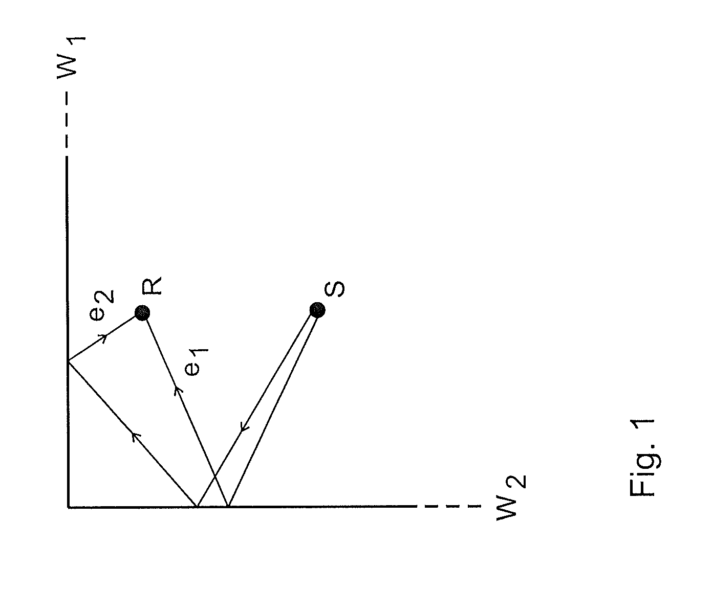
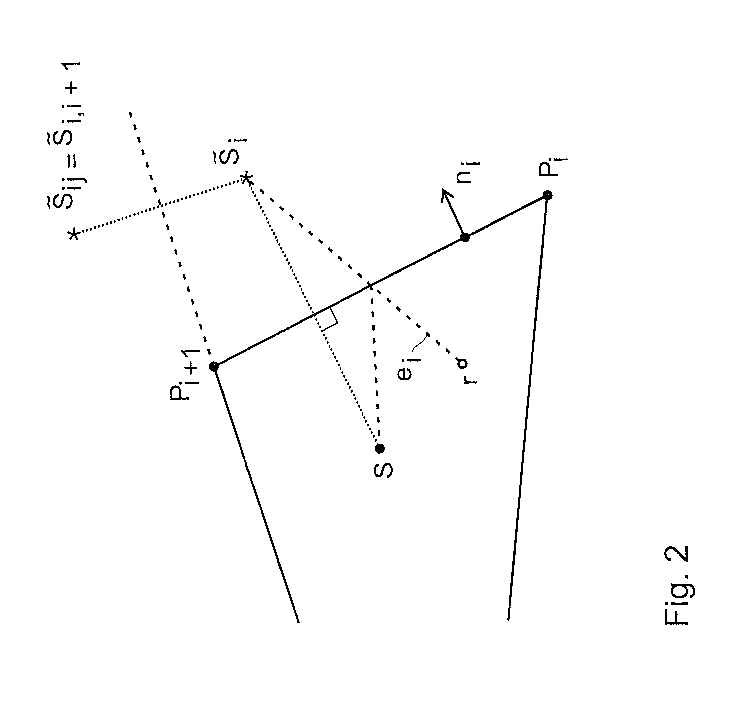
[0068]The method according to the invention uses the image source model. The idea in the image source model is that if there is a sound source on one side of the wall, then the sound field on the same side can be represented as a superposition of the original sound field and the one generated by a mirror image of the source with respect to the wall.

[0069]FIG. 2 illustrates the setup and the image source model. For our purposes, a room is either a convex planar K-polygon or a K-faced convex polyhedron. With the ith side of the room we associate an outward pointing unit normal ni, and define ...


PUM


Abstract

A method for determining the geometry and / or the localisation of an object comprising the steps of:sending one or more signals by using one transmitter;receiving by one or more receivers the transmitted signals and the echoes of the transmitted signals as reflected by one or more reflective surfacesbuilding by a computing module a first Euclidean Distance Matrix (EDM) comprising the mutual positions of the receivers;adding to the EDM matrix a new row and a new column, the new row and a new column comprising time of arrivals of said echoes and computing its rank or distance to an EDM matrixdetermining the geometry and / or the position of the object based on said rank or distance.

Description

RELATED APPLICATION[0001]The present application claims the priority of the Swiss patent application CH2935 / 12 of Dec. 22, 2012, the content of which is hereby incorporated by reference.FIELD OF THE INVENTION[0002]The present invention concerns a method and a system for determining the geometry and / or the localisation of an object, e.g. of a wall, a room, a microphone, a loudspeaker or a person. The invention concerns in particular the estimation of the geometry of a room from its acoustic room impulse responses (RIR).DESCRIPTION OF RELATED ART[0003]The problem of estimating the geometry of a room from its acoustic room impulse responses (RIR) can be resumed by a question: can a person blindfolded inside a room hear the shape of the room after having snapped his fingers? In other words can the person reconstruct the 2-D or 3-D geometry of the room from the acoustic room impulse response (RIR)?[0004]Beyond the question of uniqueness, meaning that the RIR is a unique signature of a ro...

Claims


Application Information

Patent Timeline
Patent Type & Authority Applications(United States)
IPC IPC(8): G01C15/00G01B5/00G01H7/00
CPCG01S7/54G01S15/876H04S7/305G01S2015/465G01S7/539G01S15/46G01B5/00G01C15/00G01H7/00G01S15/06G01S15/42G01S17/06H04R1/08H04R29/005
Inventor DOKMANIC, IVANPARHIZKAR, REZAWALTHER, ANDREASVETTERLI, MARTINLU, YUE
Owner ECOLE POLYTECHNIQUE FEDERALE DE LAUSANNE (EPFL)
Learn More