Variable speed dual fueled engine and electrical power management apparatus and methods

Inactive Publication Date: 2014-07-03
GENERAL ELECTRIC CO
View PDF17 Cites 8 Cited by
  • Summary
  • Abstract
  • Description
  • Claims
  • Application Information

AI Technical Summary

Benefits of technology

[0009]In embodiments, a fuel system is provided for use with a variable speed dual fuel engine. The fuel system comprises a first fuel injector configured for supplying diesel fuel to the engine, a second fuel injector configured for supplying natural gas to the engine, and a fuel controller configured to implement a diesel injection schedule and a natural gas injection schedule based on at least a fuel map, an optimal engine speed, and a current engine speed.
[0010]In other embodiments, a variable speed dual fuel engine is configured for driving connection to an electrical generator for electrical power generation. The variable speed dual fuel engine includes a combustion chamber and a fuel system for supplying fuel into the combustion chamber. The fuel system comprises a first fuel injector configured for supplying diesel fuel to the combustion chamber, a second fuel injector configured for supplying natural gas to the combustion chamber, and a fuel controller. The fuel controller is configured to establish an optimization priority and a starting fuel selection, to select one or more fuel maps based upon the optimization priority and the starting fuel selection, to determine an optimal engine speed based at least on the one or more fuel maps and on at least one engine load parameter, and to determine at least one fuel injection schedule for the first fuel injector and for the second fuel injector based on the one or more fuel maps, the optimal engine speed, and a current shaft speed.
[0011]In other embodiments, an electrical power generation and distribution system comprises a variable speed dual fuel engine, an electrical generator configured to be driven by the variable speed dual fuel engine, and an electrical power management system connected to monitor and control electrical connection of

Problems solved by technology

However, compression ignition engines may have increased emissions (e.g., nitrogen oxides (NOx), particulates, or the like), as compared to other internal combustion engines.
Therefore, maintaining constant speed regardless of load, under the current state of the art, results in prime movers typically operating away from

Method used


Image

  • Variable speed dual fueled engine and electrical power management apparatus and methods
  • Variable speed dual fueled engine and electrical power management apparatus and methods
  • Variable speed dual fueled engine and electrical power management apparatus and methods

Examples


Embodiment Construction

[0024]Reference will be made below in detail to exemplary embodiments of the invention, examples of which are illustrated in the accompanying drawings. Wherever possible, the same reference characters used throughout the drawings refer to the same or like parts, without duplicative description.

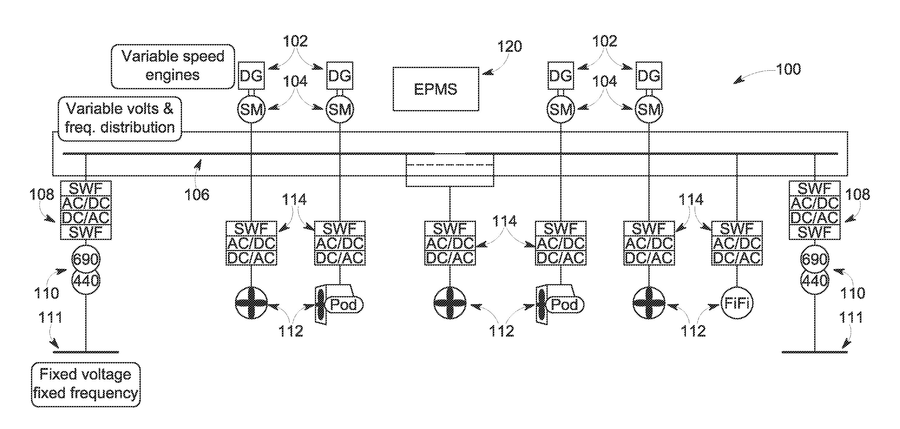
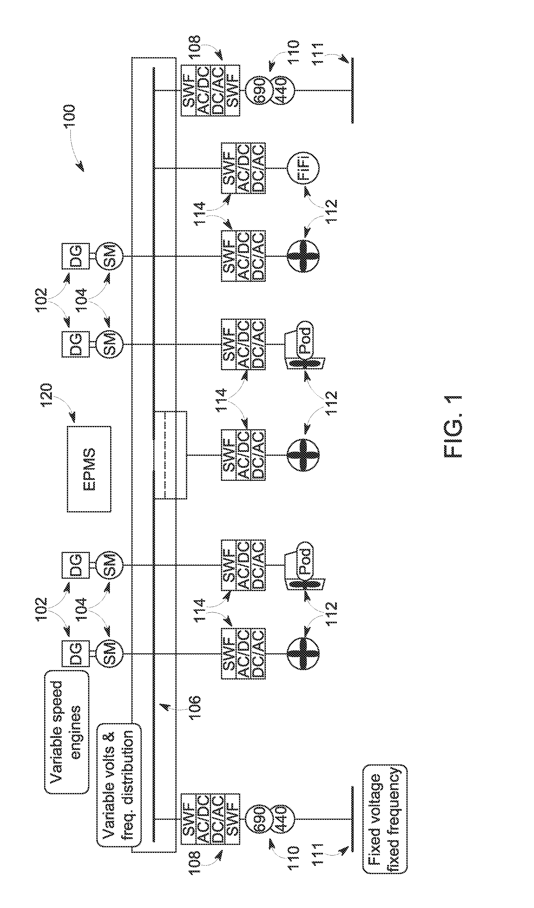
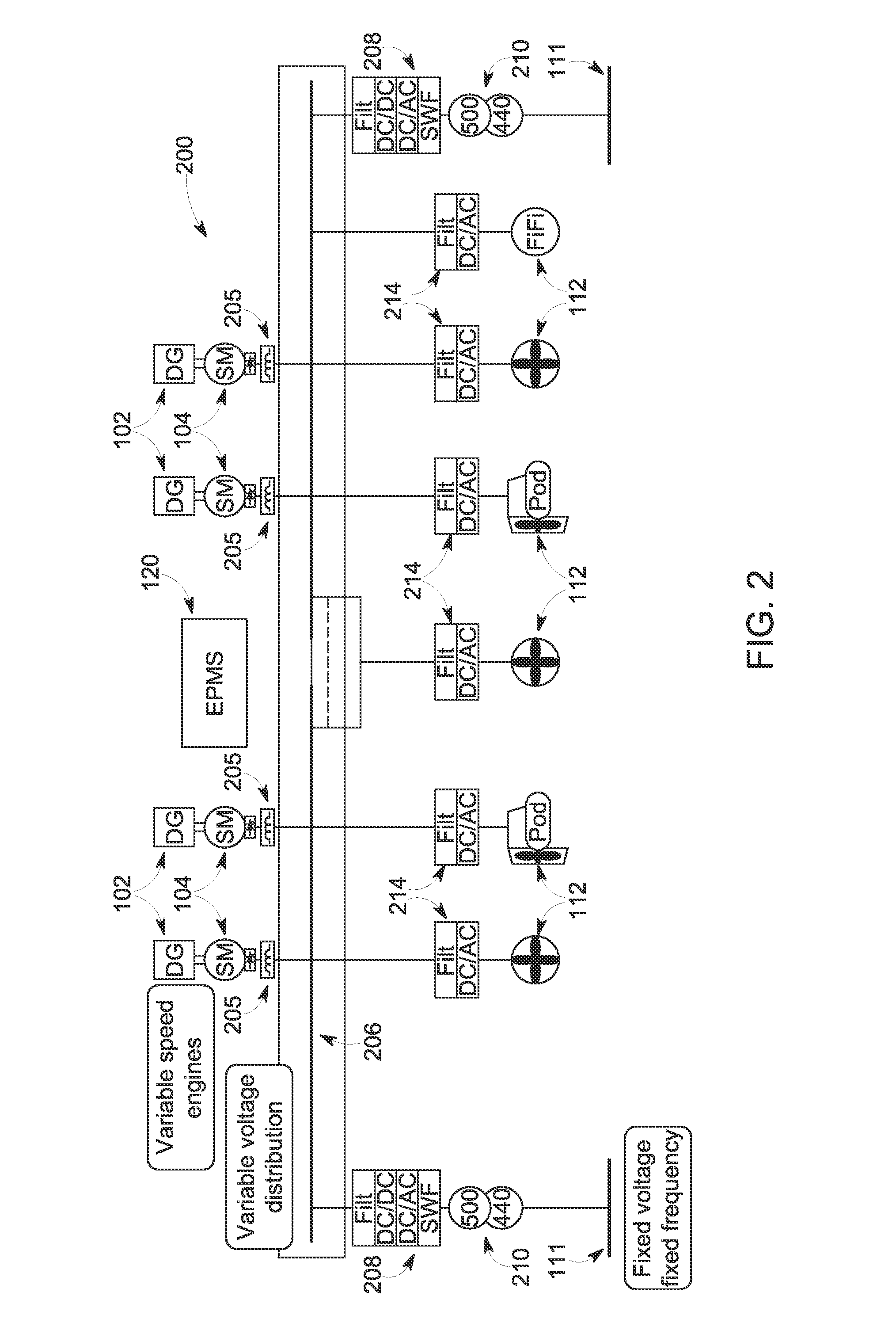
[0025]Aspects of the invention relate to variable speed power generation. Certain aspects of the invention relate to use of variable speed natural gas-fueled engines for variable speed power generation. Operation of a prime mover at variable speed (frequency) enables system optimization for a given operational priority e.g., fuel use for a given load requirement, reduction of system noise, and optimization for emissions. Thus, variable speed prime mover operation can allow more fuel-efficient power production by enabling a prime mover to better track its MCR curve. Under variable speed operation, typically, engine speed is decreased as load is decreased, and vice versa. In some embodiments of ...


PUM


Abstract

A fuel system is provided for use with a variable speed dual fuel engine. The fuel system comprises a first fuel injector configured for supplying diesel fuel to the engine, a second fuel injector configured for supplying natural gas to the engine, and a fuel controller configured to implement a diesel injection schedule and a natural gas injection schedule based on at least a fuel map, an optimal engine speed and a current engine speed.

Description

CROSS REFERENCE TO RELATED APPLICATIONS[0001]This application claims the benefit of U.S. Provisional App. No. 61 / 747,329, filed Dec. 30, 2012, which is hereby incorporated by reference in its entirety.BACKGROUND[0002]1. Technical Field[0003]Embodiments of the invention relate generally to power generation and distribution. Other embodiments relate to power generation using a dual fueled engine (e.g., diesel and liquid natural gas) and a variable speed generator.[0004]2. Discussion of Art[0005]Compression ignition engines (e.g., diesel engines) are a type of internal combustion engine which use heat of compression to initiate ignition and burn fuel. Compression ignition engines may have a higher thermal efficiency than other internal combustion engines, such as spark ignition engines, for example. However, compression ignition engines may have increased emissions (e.g., nitrogen oxides (NOx), particulates, or the like), as compared to other internal combustion engines. The increased ...

Claims


Application Information

Patent Timeline
IPC IPC(8): F02D41/38
CPCF02D41/38F02D41/1406F02D29/06F02D41/0025F02D41/0027F02D41/008F02D41/2422F02D31/001Y02T10/30
Inventor VEIT, FRANKLARSON, BRANDONGEMIN, PAULKRISHNAN, RAMESHBUTCHER, MARTINPRIMUS, ROYPRASAD, REKHA
Owner GENERAL ELECTRIC CO
Why Eureka
Try Eureka