Motor and manufacturing method thereof

a manufacturing method and motor technology, applied in the direction of windings, dynamo-electric components, and associations with control/drive circuits, can solve the problems of increasing manufacturing costs, and achieve the effect of convenient automation and easy manufacturing

Inactive Publication Date: 2014-07-03
SAMSUNG ELECTRO MECHANICS CO LTD
View PDF0 Cites 18 Cited by
  • Summary
  • Abstract
  • Description
  • Claims
  • Application Information

AI Technical Summary

Benefits of technology

[0013]An aspect of the present invention provides a motor which is easily ma

Problems solved by technology

Also, since the process of inserting a coil into the control b

Method used


Image

  • Motor and manufacturing method thereof
  • Motor and manufacturing method thereof
  • Motor and manufacturing method thereof

Examples


Embodiment Construction

[0030]Embodiments of the present invention will now be described in detail with reference to the accompanying drawings. The invention may, however, be embodied in many different forms and should not be construed as being limited to the embodiments set forth herein. Rather, these embodiments are provided so that this disclosure will be thorough and complete, and will fully convey the scope of the invention to those skilled in the art. In the drawings, the shapes and dimensions of elements may be exaggerated for clarity, and the same reference numerals will be used throughout to designate the same or like components.

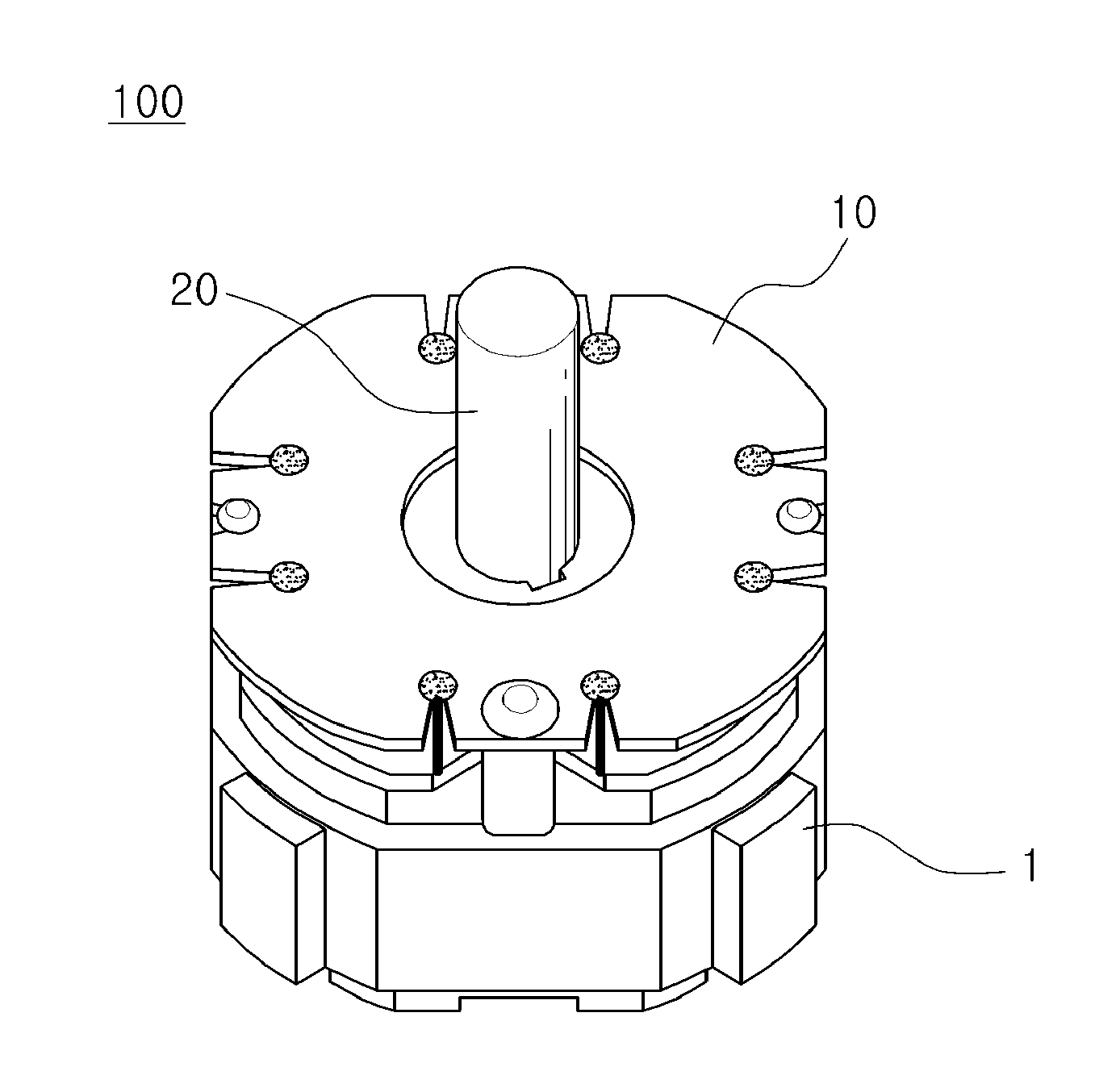
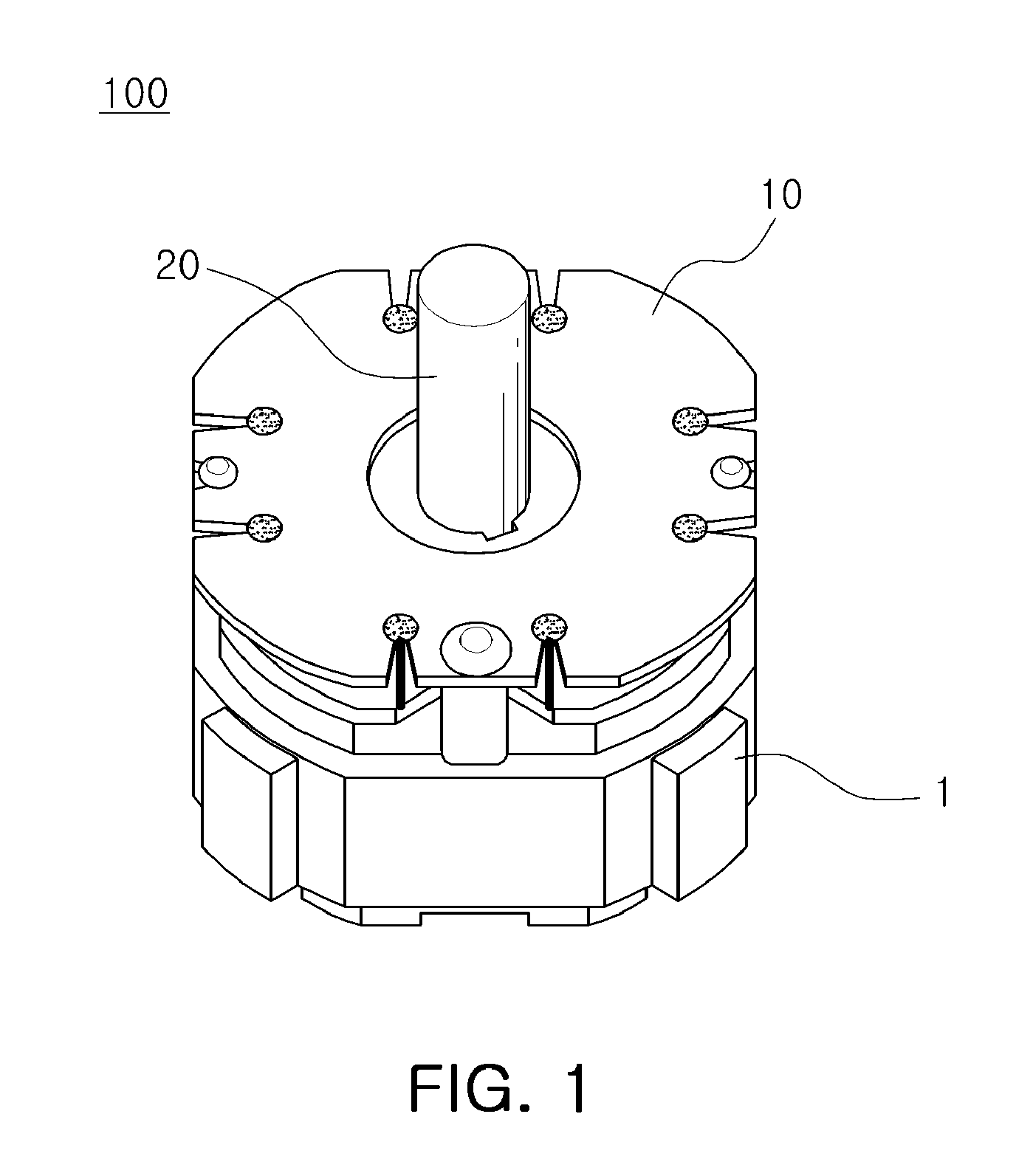
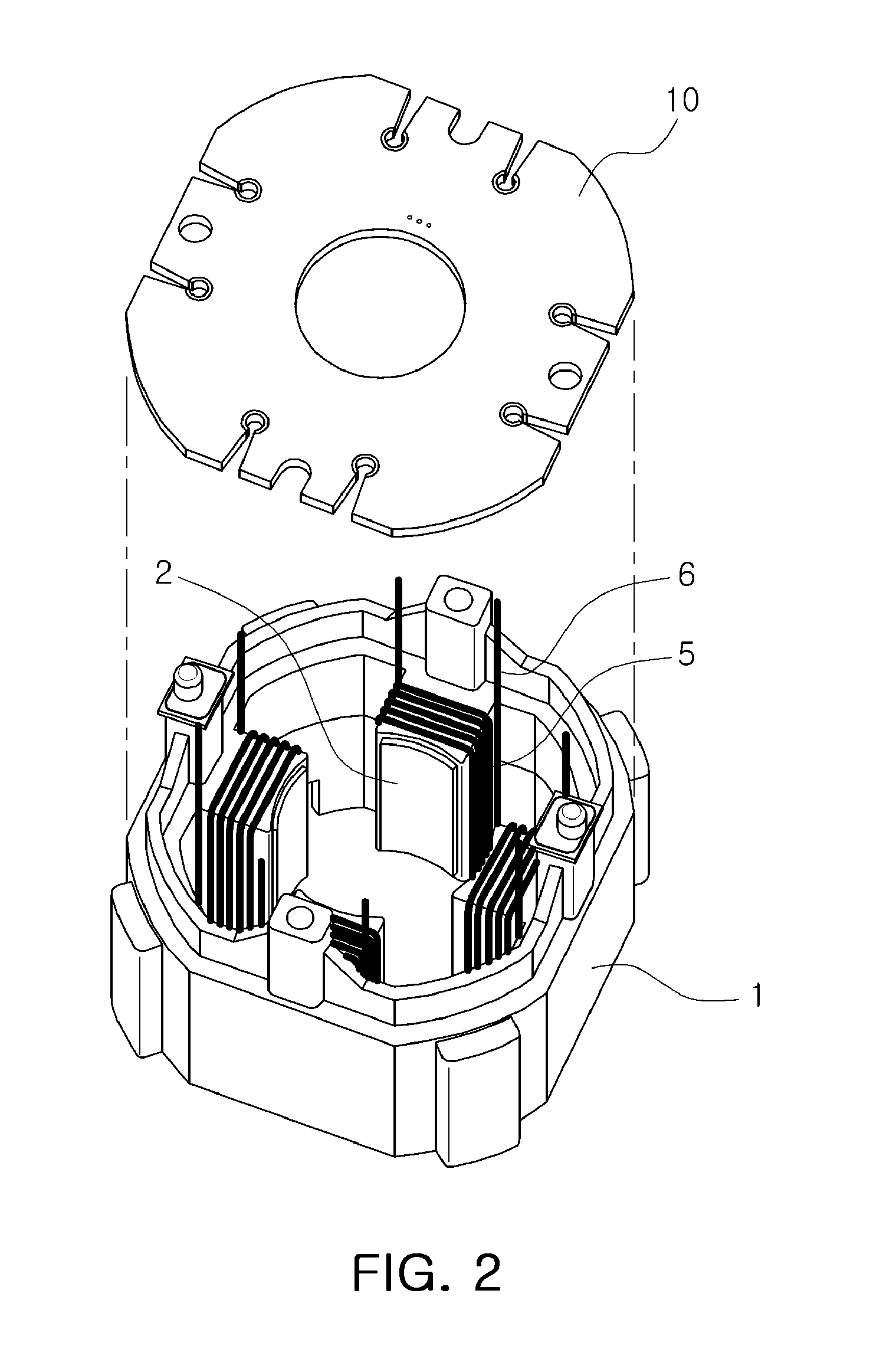
[0031]FIG. 1 is a perspective view schematically illustrating a motor according to an embodiment of the present invention. FIG. 2 is an exploded perspective view schematically illustrating the motor of FIG. 1. FIG. 3 is a plan view schematically illustrating a control board of FIG. 1. FIG. 4 is an enlarged view of portion‘A’ in FIG. 3.

[0032]Referring to FIGS. 1 through 4, ...


PUM

PropertyMeasurementUnit
Diameteraaaaaaaaaa
Widthaaaaaaaaaa

Abstract

There are provided a switched reluctance motor which can be easily manufactured and available for automation, and a manufacturing method thereof. The motor includes: a stator with a coil wound therearound; and a control board coupled to one side of the stator, the coil being electrically connected to the control board, wherein the control board includes a coupling recess in which the coil is fixedly bonded and a guide recess allowing the coil to be moved into the coupling recess from the outside of the control board.

Description

CROSS-REFERENCE TO RELATED APPLICATIONS[0001]This application claims the priority of Korean Patent Application No. 10-2012-0155288 filed on Dec. 27, 2012, in the Korean Intellectual Property Office, the disclosure of which is incorporated herein by reference.BACKGROUND OF THE INVENTION[0002]1. Field of the Invention[0003]The present invention relates to a motor and a manufacturing method thereof, and more particularly, to a switched reluctance motor which can be easily manufactured and that is available for automation, and a manufacturing method thereof.[0004]2. Description of the Related Art[0005]In a general switched reluctance motor (SRM), torque is generated by controlling power supplied to a coil wound around a multi-phase stator.[0006]Here, forward torque may be generated by magnetic pull by sequentially varying an excitation state between a rotor and a stator, and when a particular excitation state is not varied, the rotor may be stopped at a predetermined position. Also, var...

Claims


Application Information

Patent Timeline
IPC IPC(8): H02K3/32H02K15/00
CPCH02K15/0068H02K3/32H02K3/522H02K2203/03H02K11/33Y10T29/49009H02K3/28H02K5/22
Inventor SEO, SANG HOJUNG, SUNG TAICHO, YONG WANOH, MYUNG GEUNYOON, HEE SOO
Owner SAMSUNG ELECTRO MECHANICS CO LTD
Why Eureka
Try Eureka