Lighting Apparatus

a technology of light-emitting elements and light-emitting components, which is applied in the direction of light-emitting apparatus, semiconductor devices for light sources, discharge tube main electrodes, etc., can solve the problems of time and cost required for installation, the performance of light-emitting elements and their lifetime drop, and the inability to convert 100% of energy into electricity, etc., to achieve efficient radiation, compact and lightweight

Inactive Publication Date: 2014-07-03
MOLEX JAPAN +1
View PDF1 Cites 12 Cited by
  • Summary
  • Abstract
  • Description
  • Claims
  • Application Information

AI Technical Summary

Benefits of technology

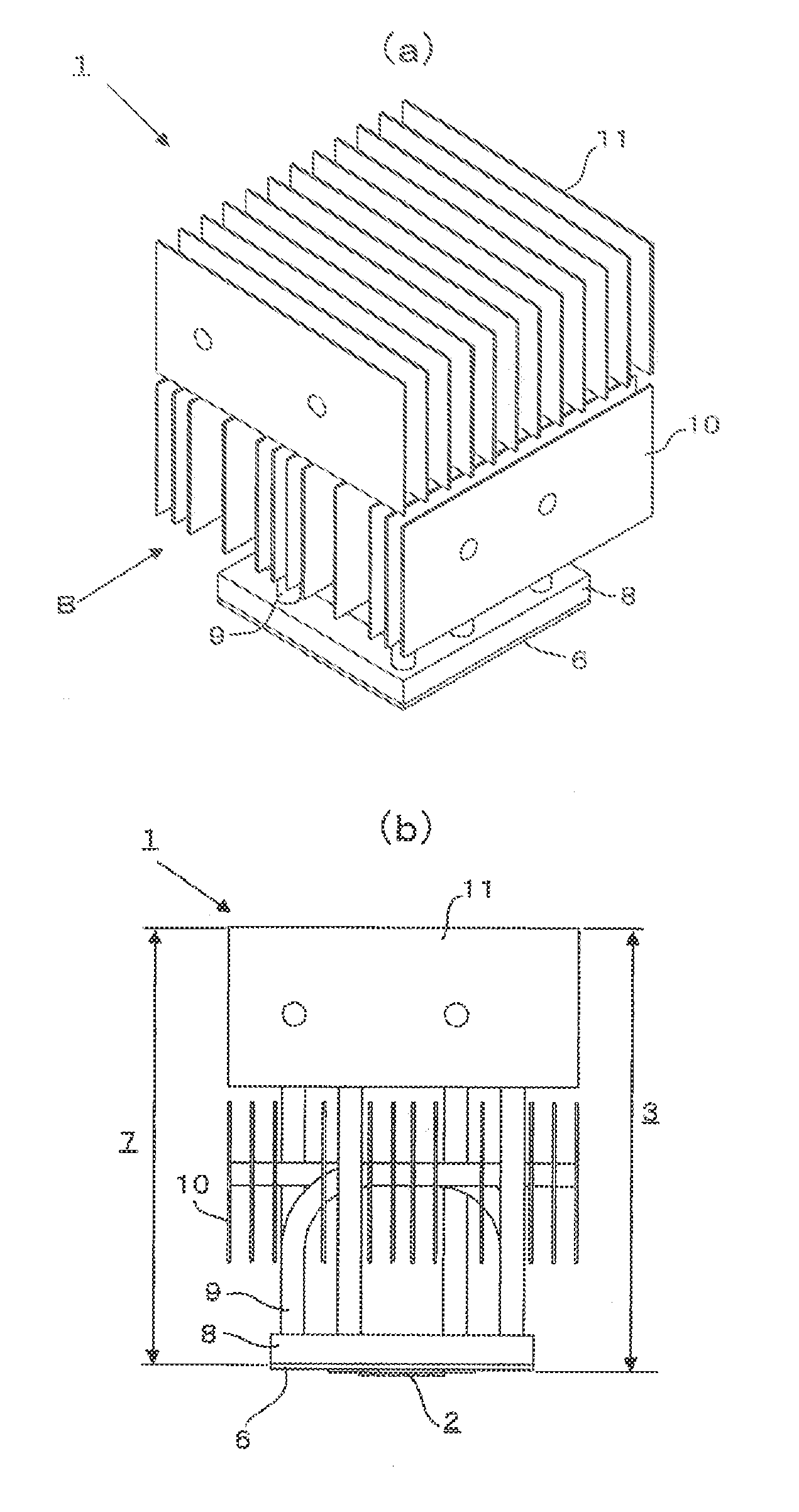
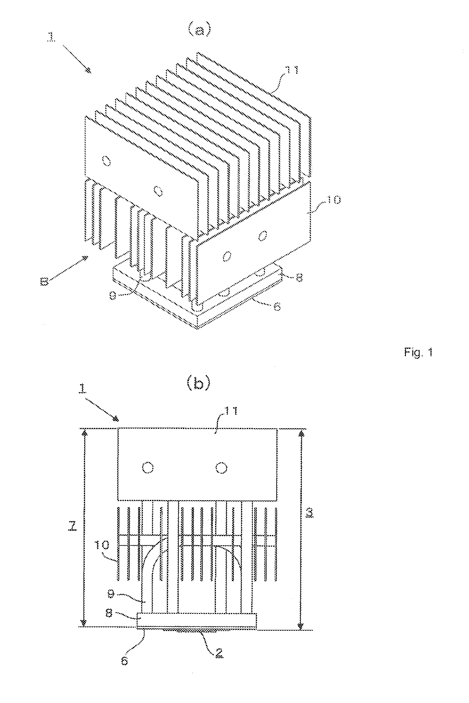
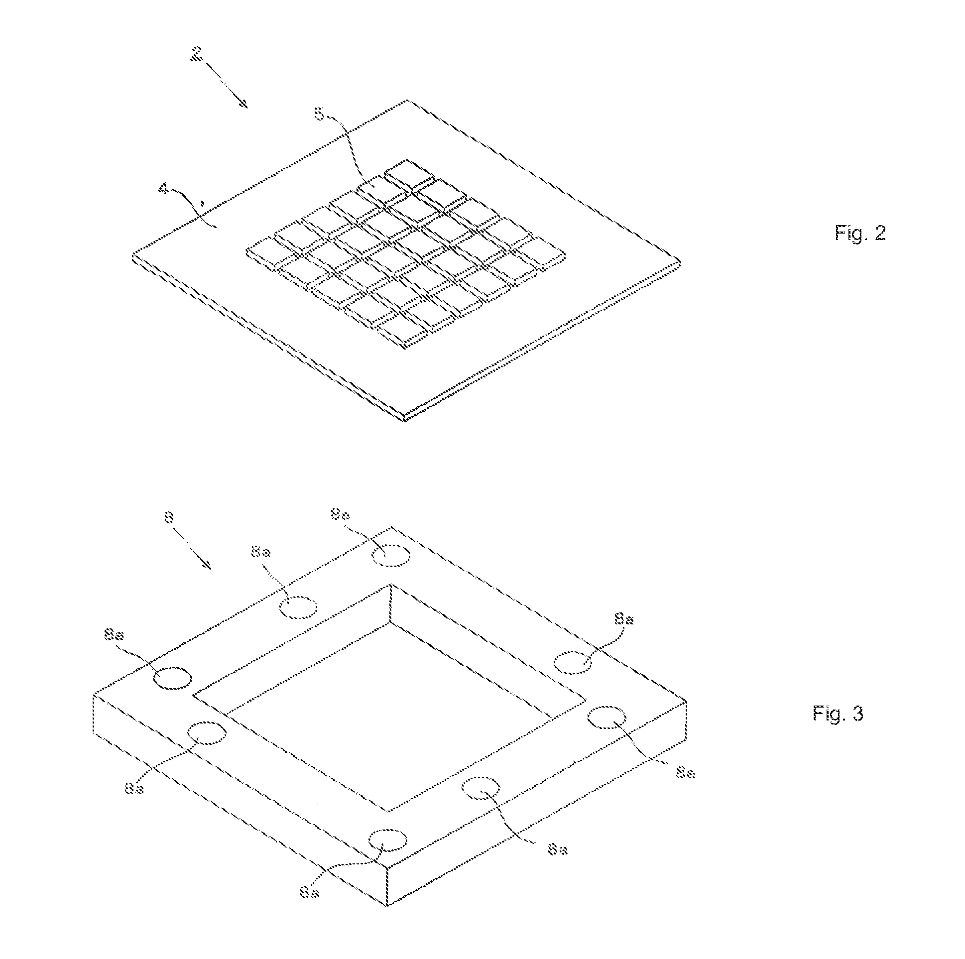
[0010]The Present Disclosure came about in consideration of the above background and has as an object to provide a compact and lightweight lighting apparatus that is able to emit high-intensity light. In order to achieve the aforementioned object, the lighting apparatus according to the Present Disclosure comprises a light-emitting element, a heat-diffusing member in heat-conductive contact with the light-emitting element that diffuses the heat conducted from the light-emitting element, a heat-transporting member with one end in heat-conductive contact with the heat-diffusing member that transports heat from the one end to its other end, and a heat-radiating member in heat-conductive contact with the other end of the heat-transporting member that radiates the heat conducted from the heat-transporting member into the environment. The heat-diffusing member may have a central portion that faces the light-emitting element and a surrounding portion that encloses all or part of the central portion. The heat-transporting member may be in heat-conductive contact with the heat-diffusing member in the surrounding portion.
[0014]With the Present Disclosure, the lighting apparatus is provided with heat-diffusing members, heat-transporting members and heat-radiating members, so the heat generated by the light-emitting element can be efficiently radiated into the environment, and thus the lighting apparatus can be made more compact and lightweight. In addition, the lighting apparatus is able to emit high-intensity light. For that reason, it is possible to install lighting apparatus able to emit high-intensity light even in small spaces.

Problems solved by technology

As defined above, the light-emitting element is an apparatus that converts electrical energy into visible light, but the efficiency of conversion thereof is not 100%.
In addition, when the temperature of the light-emitting element increases, the performance of the light-emitting element and its lifetime drop.
However, with the lighting apparatus of the '888 Application, cooling water runs through the water pipe, so there are problems with the time and costs required for installation.
In addition, there is also a problem in that if the cooling water is allowed to run off; namely, if the cooling water, heated after absorbing the heat generated by the light-emitting element, is dumped as is, then the amount of cooling water consumed would be large.
Although the amount of cooling water consumed can be reduced by recirculating the cooling water using an apparatus that releases the heat absorbed by the cooling water into the environment (e.g., a radiator), not only would this make the entire apparatus large but there is also the problem of the costs also becoming greater.
However, the transport of heat generated by the light-emitting element to the heat sink is done by conduction of heat within a solid, so there is a limit to the heat-conduction performance.
In addition, no particular consideration is given to the flow of air in the periphery of the heat sink, so there is a limit to the heat-radiation performance also.
For this reason, there is a problem in that if one wishes to obtain the desired cooling capacity, the outside dimensions of the cooling means must be made greater.
In addition, outside dimensions of the conventional lighting apparati with cooling means are limited by the conditions of the installation location, so they cannot be made infinitely large.
Ultimately, the intensity of the lighting apparatus are also limited by the conditions of the installation location.
Thus, regarding the aforementioned Japanese Patent Applications, the problem is that apparati able to emit high-intensity light cannot be installed in small spaces.

Method used


Image

  • Lighting Apparatus
  • Lighting Apparatus
  • Lighting Apparatus

Examples


Embodiment Construction

[0026]While the Present Disclosure may be susceptible to embodiment in different forms, there is shown in the Figures, and will be described herein in detail, specific embodiments, with the understanding that the Present Disclosure is to be considered an exemplification of the principles of the Present Disclosure, and is not intended to limit the Present Disclosure to that as illustrated.

[0027]As such, references to a feature or aspect are intended to describe a feature or aspect of an example of the Present Disclosure, not to imply that every embodiment thereof must have the described feature or aspect. Furthermore, it should be noted that the description illustrates a number of features. While certain features have been combined together to illustrate potential system designs, those features may also be used in other combinations not expressly disclosed. Thus, the depicted combinations are not intended to be limiting, unless otherwise noted.

[0028]In the embodiments illustrated in ...


PUM


Abstract

A lighting apparatus is provided with: a light-emitting unit, a heat spreader in heat-conductive contact with the light-emitting unit that diffuses the heat conducted from the light-emitting unit, heat pipes with one end in heat-conductive contact with the heat spreader that transport heat to their other end, and a lower row of cooling fins and upper row of cooling fins that are in heat-conductive contact with the other ends of the heat pipes, and that radiate the heat conducted from the heat pipes into the environment.

Description

REFERENCE TO RELATED APPLICATIONS[0001]The Present Disclosure claims priority to Japanese Patent Application No. 2011-287839, entitled “Lighting Apparatus,” and filed 28 Dec. 2011 with the Japanese Patent Office. The content of this Application is incorporated in its entirety herein.BACKGROUND OF THE PRESENT DISCLOSURE[0002]The Present Disclosure relates, generally, to a lighting apparatus, and, more particularly, to a lighting apparatus provided with a heat-radiating means which suppresses any increase in the temperature of the light-emitting element.[0003]An apparatus equipped with a light-emitting element that provides illumination by means of visible light emitted by the light-emitting element is called a “lighting apparatus.” Generally, the light-emitting element refers to a light-emitting diode (LED) or other solid-state light-emitting element, but in this Specification, it refers to an entire apparatus that converts electrical energy into emitted visible light. Accordingly, i...

Claims


Application Information

Patent Timeline
Patent Type & Authority Applications(United States)
IPC IPC(8): F21V29/00
CPCF21V29/004F21K9/00F28D15/0275F28F1/32F21V29/71F21V29/717F21V29/74F21V29/75F21V29/76F21V29/763F21V29/773F21Y2105/10F21Y2115/10
Inventor MIZUTA, KEI
Owner MOLEX JAPAN
Why Eureka
Try Eureka