Virtual image displaying system

a virtual image and display system technology, applied in the field of virtual image display system, can solve the problems of difficult placement of virtual images directly onto the desktop, and conventional virtual image display system can only provide small-size displaying frames

Active Publication Date: 2014-07-03
DELTA ELECTRONICS INC
View PDF2 Cites 0 Cited by
  • Summary
  • Abstract
  • Description
  • Claims
  • Application Information

AI Technical Summary

Benefits of technology

[0014]An objective of the present invention is to provide a virtual image displa

Problems solved by technology

However, the conventional virtual image displaying system has a bulky volume and occupies a large space, so the location where it is placed is limited and this mak

Method used


Image

  • Virtual image displaying system
  • Virtual image displaying system
  • Virtual image displaying system

Examples


first embodiment

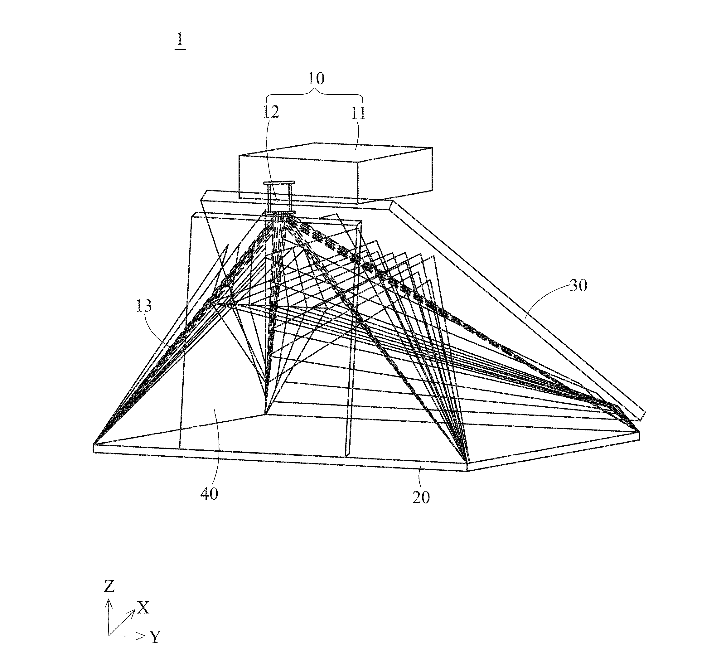
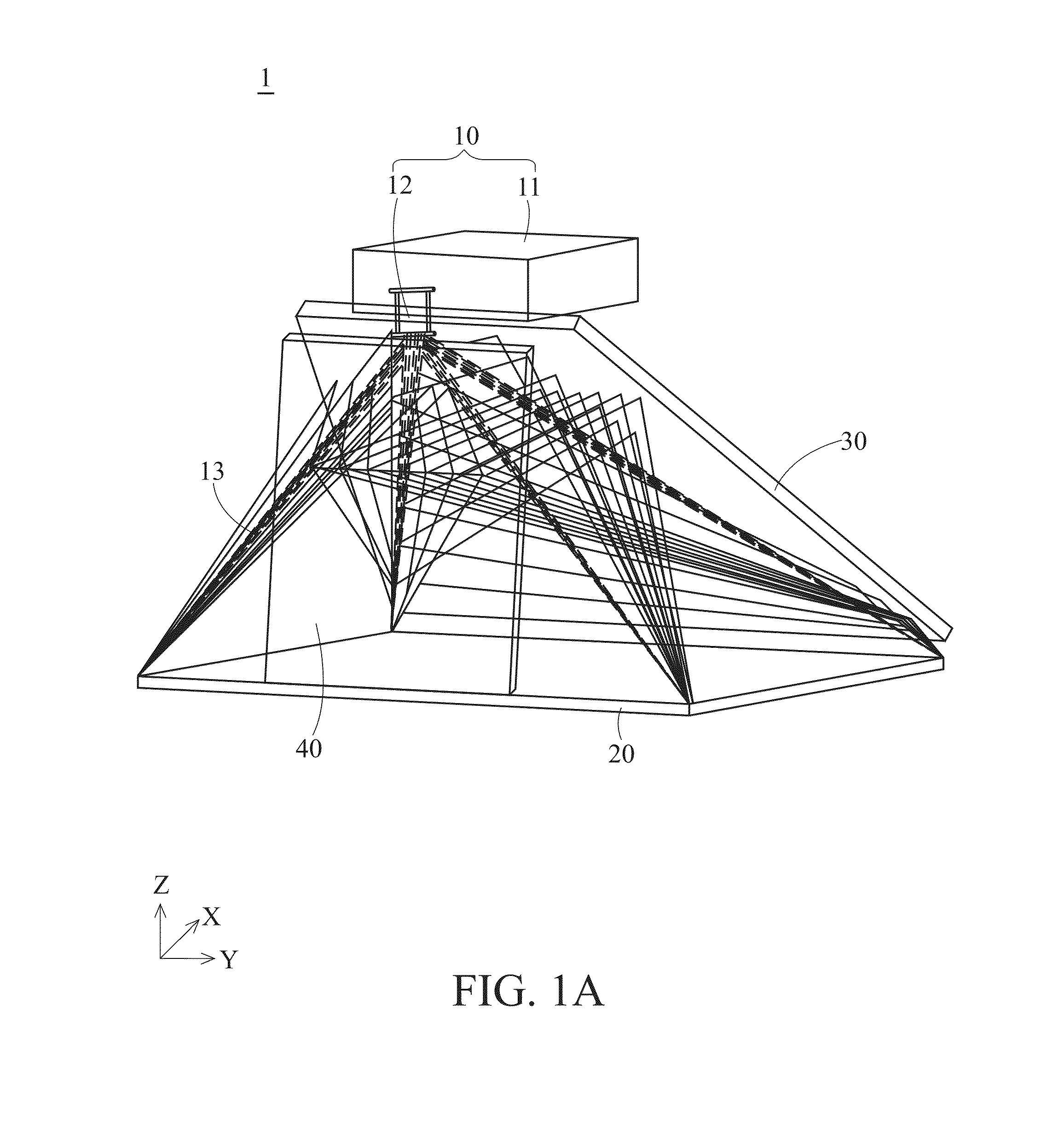
[0030]In the present invention, a virtual image displaying system 1 is proposed. The virtual image displaying system 1 is disposed in a space which has a first direction X, a second direction Y and a third direction Z that are perpendicular to one another. The first direction X and the second direction Y may be horizontal directions, while the third direction Z may be a vertical direction.

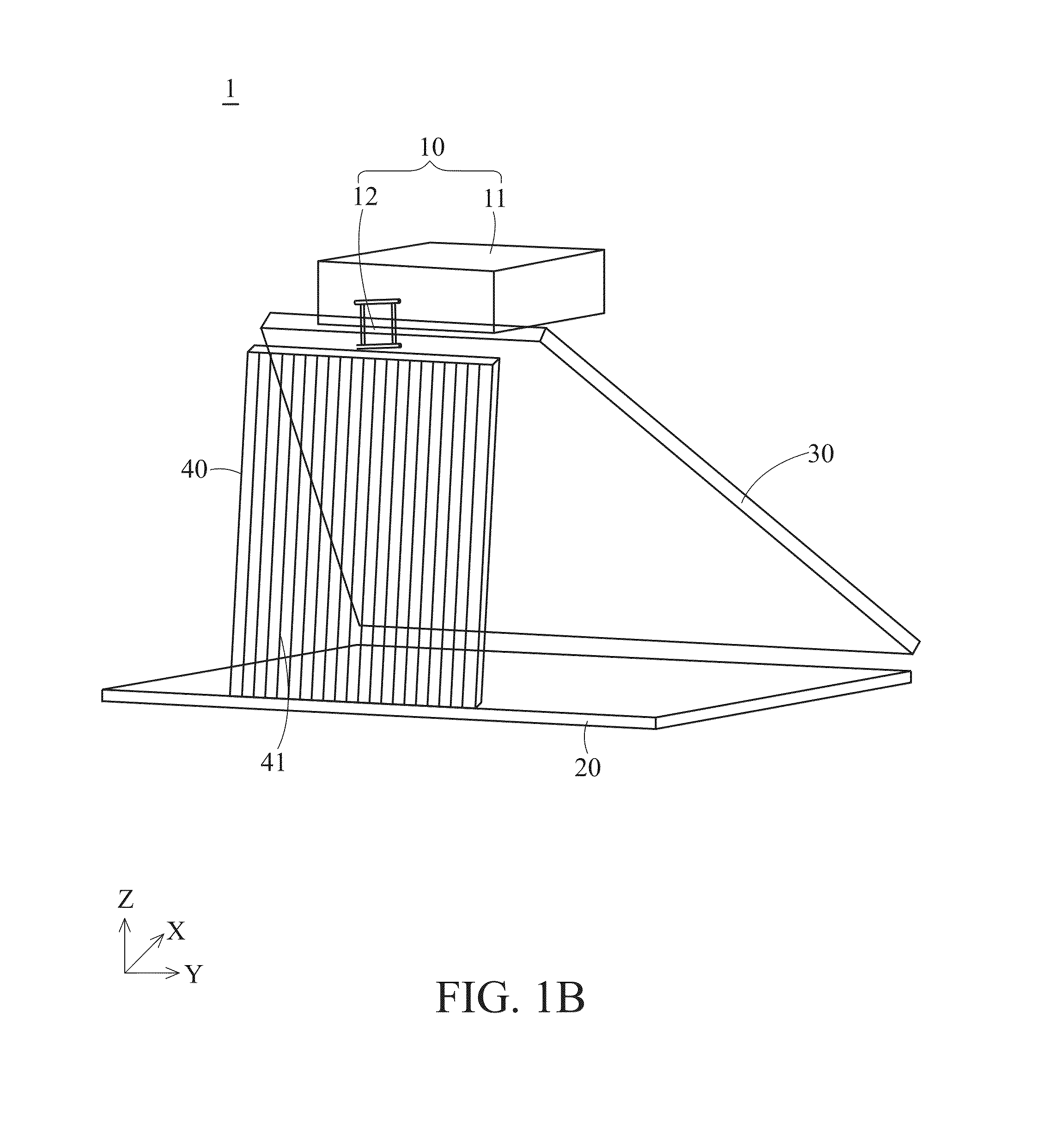
[0031]The virtual image displaying system 1 comprises a projector 10, an optical relaying structure 20, a reflective mirror 30 and a slit array 40. The technical contents of these components will be described sequentially as follows.

[0032]The projector 10 has a main body 11 and a projection lens 12 which is connected to the main body 11. As a major part of the projector 10, the main body 11 comprises primary components such as a light source and an imaging device (e.g., DMD). The main body 11 can produce a light beam (i.e., an image) 13 propagating to the projection lens 12 which then outputs the l...

second embodiment

[0050]FIG. 8 is a schematic plan view of a virtual image displaying system according to the second preferred embodiment of the present invention. In the second embodiment, another virtual image displaying system 2 is proposed. The virtual image displaying system 2 is generally identical to the virtual image displaying system 1 but is different from the virtual image displaying system 1 in that the main body 11 of a projector 10 of the virtual image displaying system 2 is inclined relative to an optical relaying structure 20 as with the reflective mirror 30. An inclining angle of the main body 11 may be identical to that of the reflective minor 30. By disposing the main body 11 of the projector 10 to be inclined, the overall volume of the virtual image displaying system 2 can be further reduced. Other technical features and effects of the virtual image displaying system 2 are identical or similar to those of the virtual image displaying system 1 and, thus, will not be described again...


PUM


Abstract

A virtual image displaying system is disclosed and includes: a projector, an optical relaying device, a reflective mirror and a slit array. The projector has a main body and a projection lens connecting to the main body. The main body outputs a light beam by the projection lens. The optical relaying device faces the projection lens and is disposed under the projection lens. The reflective mirror is inclined relative to and disposed above the optical relaying device. The slit array is inclined relative to and disposed in front of the reflective mirror. The projection lens is further disposed between the reflective mirror and the slit array. Therefore, the virtual image displaying system has a compact configuration of components.

Description

CROSS-REFERENCES TO RELATED APPLICATIONS[0001]This application claims priority to Taiwan Patent Application No. 101150748 filed on Dec. 28, 2012, which is hereby incorporated herein by reference in its entirety.BACKGROUND OF THE INVENTION[0002]1. Field of the Invention[0003]The present invention provides a displaying system, and more particularly, to a virtual image displaying system.[0004]2. Descriptions of the Related Art[0005]Over recent years, stereoscopic image displays have become a hot topic in research. The primary principle of stereoscopic image displays is as follows: a left-eye view-angle image and a right-eye view-angle image are fed by a display apparatus to the left eye and the right eye of a viewer respectively. Then, when the two images with the same image content but different parallaxes are viewed by both eyes of the viewer, depth will be perceived in the resulting image by the viewer because of the visual characteristics of the human eye. Thus, the resulting image...

Claims


Application Information

Patent Timeline
IPC IPC(8): G02B27/22G02F1/13
CPCG02F1/1313G02B27/22A61B5/742G02B30/35
Inventor HUANG, JUNEJEI
Owner DELTA ELECTRONICS INC
Why Eureka
Try Eureka