
Vehicle-mounted cargo inspection system

a cargo inspection and vehicle-mounted technology, applied in the direction of measurement devices, nuclear radiation detection, instruments, etc., can solve the problems of unfavorable inspection of the contents of every container, and the inability of conventional chassis types to operate, so as to reduce maintenance costs, facilitate operation, and ensure the effect of safety

Inactive Publication Date: 2014-07-03
L3 COMMUNICATIONS SECURITY & DETECTION SYSTEMS CORPORATION
View PDF9 Cites 3 Cited by
  • Summary
  • Abstract
  • Description
  • Claims
  • Application Information

AI Technical Summary

Benefits of technology

The inventors have discovered that by reducing the weight of a system, it can be mounted on a chassis that doesn't have rails running from front to back. This even distribution of weight makes it easier to operate and safer, while also reducing costs. Additionally, the absence of chassis rails allows for the placement of an x-ray source and detector array on the opposite side of the vehicle, which improves image quality without sacrificing image quality.

Problems solved by technology

Because it is difficult to open every container and inspect its contents, inspection systems are conventionally used to detect contraband within cargo containers.
As a result, conventional vehicle-mounted inspection systems are generally truck-mounted, since a truck chassis can support the total weight of conventional systems, but other conventional chassis types cannot.
The inventors have recognized that use of a truck chassis imposes unnecessary constraints, owing mainly to the chassis rails located between the front and rear axles to accommodate the drive shaft.
However, placement of the x-ray source and detector on one side of the truck creates an uneven weight distribution from one side of the truck to the other.
The total weight of the detection components and counter weight can put the system at risk of exceeding road weight limits, as the x-ray source and detector conventionally weigh about seven metric tons in total, and the counter weight typically weighs about three metric tons.
In addition, the counter weight does not eliminate the uneven weight distribution from one side of the vehicle to the other, so this type of system is difficult to operate.
For example, the truck may veer to one side while being driven between scanning locations, which not only can detract from operator safety but can also increase the cost of maintaining the system.
Moreover, images produced by this type of system often have a perspective which make them difficult to inspect.
However, even though the x-ray source and detector array may be located on opposite sides of the truck (e.g., the x-ray source may be located on the driver's side of the truck, and the detector array may be located outside the truck's body on the passenger side), the weight of this type of system may still be somewhat unevenly distributed from one side of the truck to the other, and is very unevenly distributed from the front of the truck to the back, making the vehicle difficult to operate.
However, the additional weight of the ballast may sometimes cause the overall system to exceed certain road weight limits.

Method used


Image

  • Vehicle-mounted cargo inspection system
  • Vehicle-mounted cargo inspection system
  • Vehicle-mounted cargo inspection system

Examples


Embodiment Construction

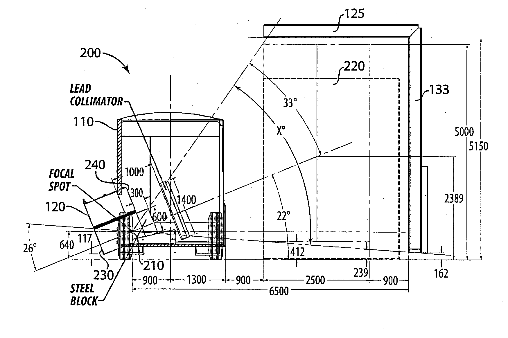
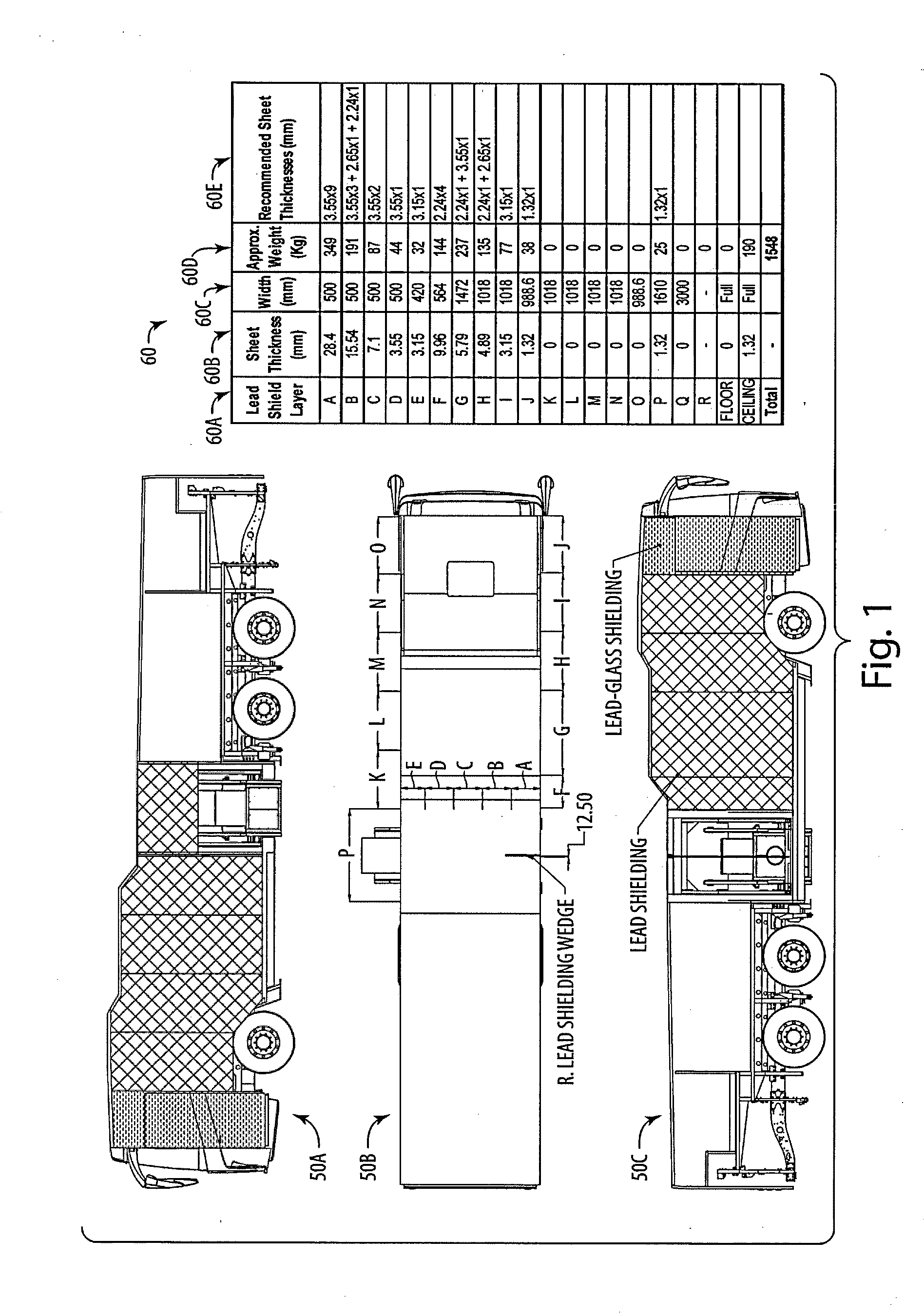
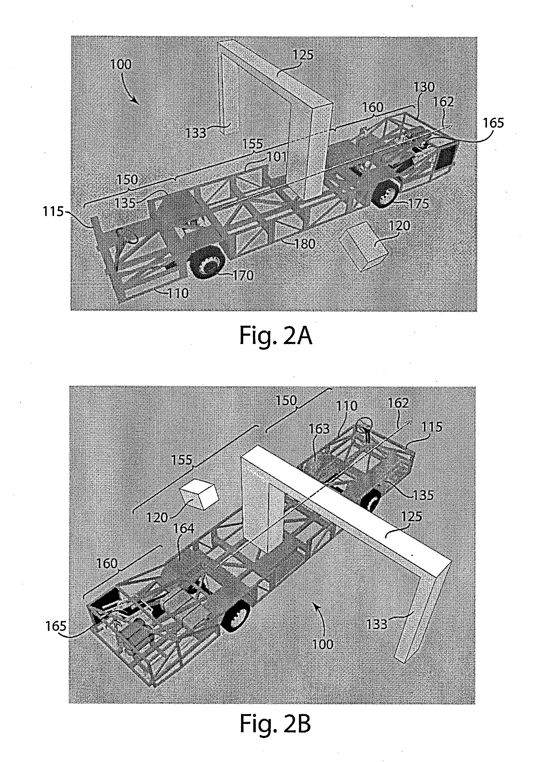
[0017]The inventors have recognized that various deficiencies of conventional vehicle-mounted inspection systems may be overcome by reducing the overall weight of the system so that it may be mounted on a vehicle chassis type which does not include rails that extend from near the front of the vehicle to near the back. As such, detection components may be placed between the front and rear axles of the vehicle, without an x-ray beam having to pass through a chassis rail, and the weight of the system may be more evenly distributed from the front of the vehicle to the back of the vehicle, making the system easier to operate, safer, and less costly to maintain than conventional systems.

[0018]Embodiments of the invention may employ any of numerous techniques to reduce overall system weight to enable use of a chassis type that does not include chassis rails extending from roughly the front of the vehicle to the back of the vehicle. For example, in some embodiments, overall system weight ma...


PUM


Abstract

Some embodiments of the invention provide a mobile cargo inspection system mounted on a vehicle chassis type which does not include rails that extend from near the front of the vehicle to near the back. As such, detection components may be placed between the front and rear axles of the vehicle without penetrating radiation having to pass through a chassis rail before reaching the cargo to be inspected. As a result, the weight of the vehicle-mounted cargo inspection system may be more evenly distributed from the front of the vehicle to the back, and from one side of the vehicle to the other, thus making the system easier to operate, safer, and less costly to maintain than conventional systems.

Description

RELATED APPLICATION[0001]This application claims the benefit under 35 U.S.C. §119(e) of the filing date of U.S. Provisional Application Ser. No. 61 / 502,612, filed Jun. 29, 2011, bearing Attorney Docket No. L0632.70112US00, entitled “COACH / BUS X-RAY CARGO VEHICLE SCANNER,” the entirety of which is incorporated herein by reference.BACKGROUND[0002]Numerous cargo containers pass through shipping terminals and other access points every day. Weapons, explosives and / or other contraband may be concealed within any one of the cargo containers. Because it is difficult to open every container and inspect its contents, inspection systems are conventionally used to detect contraband within cargo containers. Frequently, inspection systems employ penetrating radiation (e.g., x-rays) to form an image of items in a container under inspection. Specifically, by measuring the radiation after it has interacted with items in a container, an image of the items may be formed.[0003]Cargo containers are larg...

Claims


Application Information

Patent Timeline
Patent Type & Authority Applications(United States)
IPC IPC(8): G01V5/00
CPCG01V5/005G01V5/22G01V5/226
Inventor AZMI, SARFRAZBOGOSIAN, JR., JASPERREILLY, JOHN J.BARNBY, RANDY
Owner L3 COMMUNICATIONS SECURITY & DETECTION SYSTEMS CORPORATION
Learn More