
Optical receiver having a MIMO equalizer

a technology of optical receiver and equalizer, which is applied in the direction of transmission monitoring, transmission monitoring/testing/fault-measurement system, electrical apparatus, etc., can solve the problems of additional impairments at the transmitter and/or the receiver, and achieve the effect of more effective mitigation of receiver-, link-, and/or transmitter-induced signal impairments

Inactive Publication Date: 2014-07-03
ALCATEL LUCENT SAS
View PDF1 Cites 17 Cited by
  • Summary
  • Abstract
  • Description
  • Claims
  • Application Information

AI Technical Summary

Benefits of technology

The patent describes an optical receiver that has a special processing unit to fix any problems caused by the optical signal and the electrical signal processing. The processing unit uses a special technique called signal equalization that helps to remove any impurities in the signals. This makes it easier for the receiver to get the data it needs from the optical input signal.

Problems solved by technology

However, the end-to-end transmission of data may cause additional impairments at the transmitter and / or the receiver.
Furthermore, in an optical communication system with additional MIMO dimensions, such as a system that employs multimode fibers and space-division multiplexing, a relatively large number of additional circuit elements may introduce other types of signal impairments.

Method used


Image

  • Optical receiver having a MIMO equalizer
  • Optical receiver having a MIMO equalizer
  • Optical receiver having a MIMO equalizer

Examples


Embodiment Construction

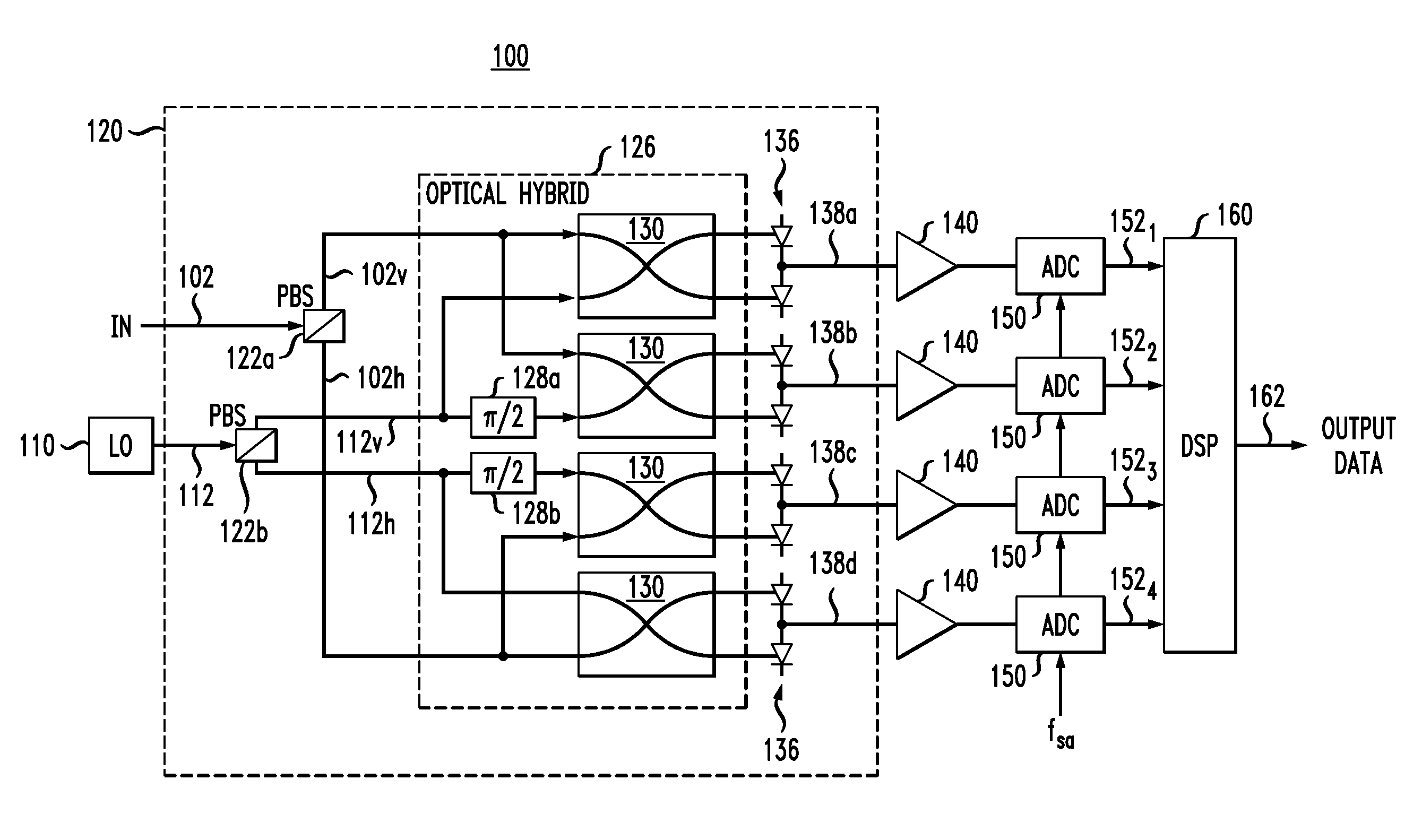
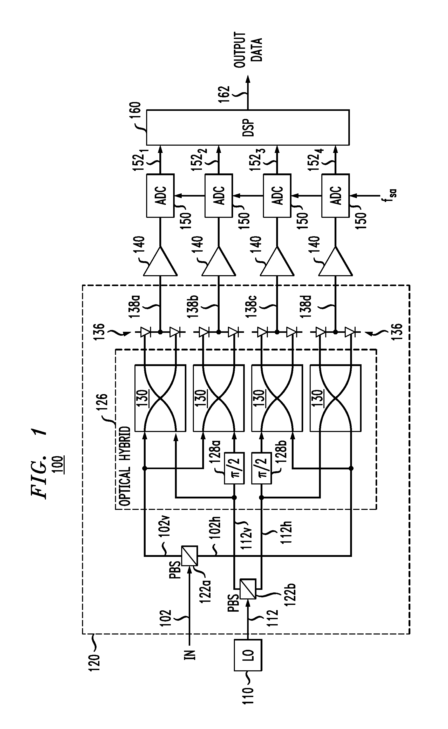
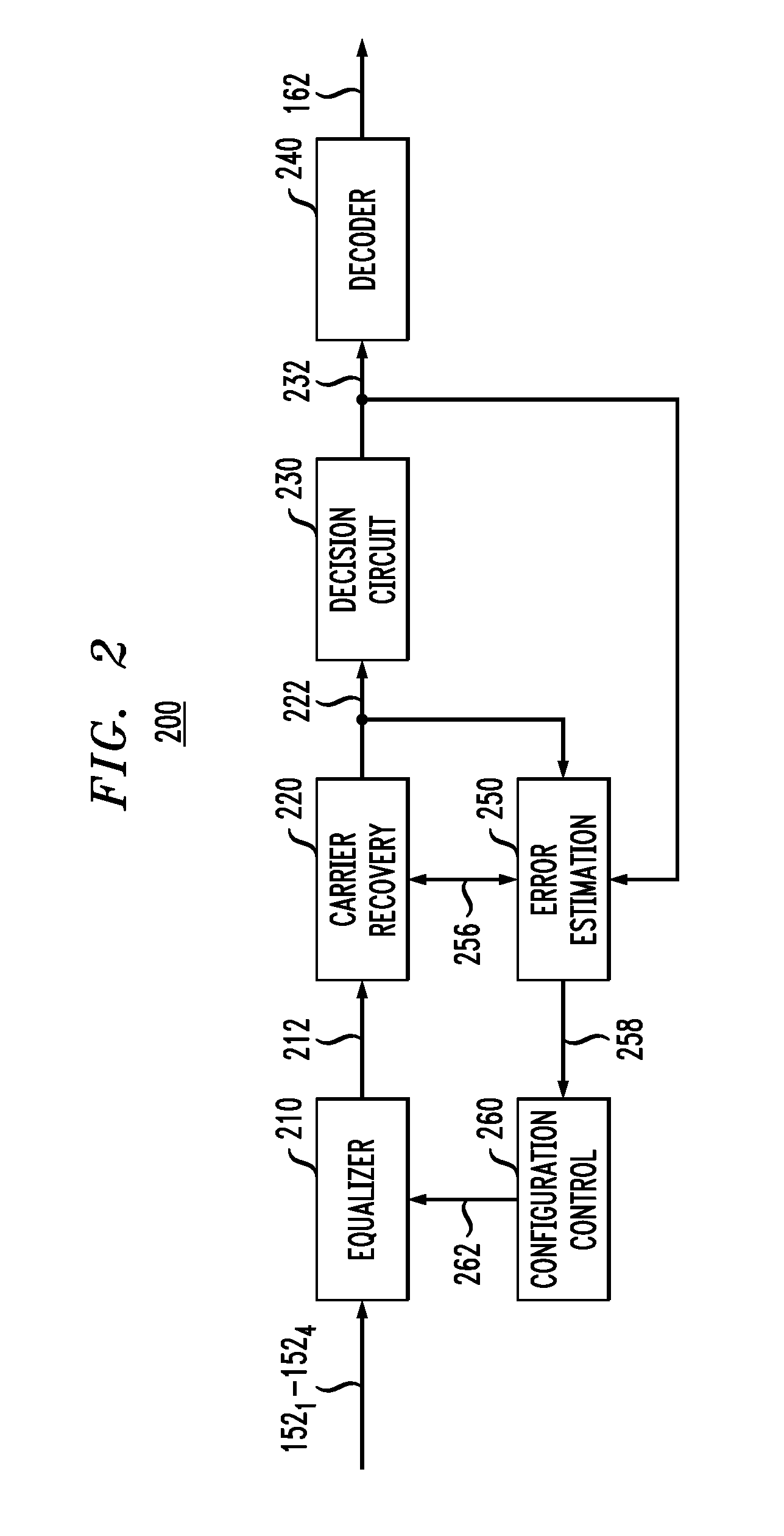
[0007]Disclosed herein are various embodiments of an optical receiver comprising an optical-to-electrical converter and a digital processor having one or more equalizer stages. The optical-to-electrical converter is configured to mix an optical input signal and an optical local-oscillator signal to generate a plurality of electrical digital measures of the optical input signal. The digital processor is configured to process the electrical digital measures to recover the data carried by the optical input signal. At least one of the equalizer stages is configured to perform signal-equalization processing in which the electrical digital measures and / or digital signals derived from the electrical digital measures are treated as linear combinations of arbitrarily coupled signals, rather than one or more pairs of 90-degree phase-locked I and Q signals. The latter feature may enable the digital processor to more-effectively mitigate the receiver-, link-, and / or transmitter-induced signal i...


PUM


Abstract

An optical receiver comprising an optical-to-electrical converter and a digital processor having one or more equalizer stages. The optical-to-electrical converter is configured to mix an optical input signal and an optical local-oscillator signal to generate a plurality of electrical digital measures of the optical input signal. The digital processor is configured to process the electrical digital measures to recover the data carried by the optical input signal. At least one of the equalizer stages is configured to perform signal-equalization processing in which the electrical digital measures and / or digital signals derived from the electrical digital measures are being treated as linear combinations of arbitrarily coupled signals, rather than one or more pairs of 90-degree phase-locked I and Q signals. The latter feature enables the digital processor to more-effectively mitigate the receiver-, link-, and / or transmitter-induced signal impairments because various orthogonality-degrading effects can be mitigated in a relatively straightforward manner.

Description

BACKGROUND[0001]1. Field[0002]The present invention relates to optical communication equipment and, more specifically but not exclusively, to multiple-input multiple-output (MIMO) signal equalization.[0003]2. Description of the Related Art[0004]This section introduces aspects that may help facilitate a better understanding of the invention(s). Accordingly, the statements of this section are to be read in this light and are not to be understood as admissions about what is in the prior art or what is not in the prior art.[0005]A coherent optical-detection scheme is capable of detecting not only the amplitude of an optical signal, but also the signal's phase. These capabilities make coherent optical detection compatible with the use of spectrally efficient modulation formats, such as quadrature-amplitude modulation (QAM) and phase-shift keying (PSK) in their various forms. Compared to non-coherent optical detectors, coherent optical detectors offer relatively easy wavelength tunability...

Claims


Application Information

Patent Timeline
Patent Type & Authority Applications(United States)
IPC IPC(8): H04B10/08
CPCH04B10/614H04B10/616
Inventor RANDEL, SEBASTIAN A.ESSIAMBRE, RENE-JEANWINZER, PETER J.RYF, ROLAND
Owner ALCATEL LUCENT SAS
Learn More