Target Device for Determining Received Hits in a Light Based Weapons Simulation System

a technology of light-based weapons and target devices, which is applied in the field of target devices for determining received hits in light-based weapons simulation systems, can solve the problems of inability to pinpoint the actual target location, the magnitude of light received at any one area of the solar cell being too weak to record a hit, and the failure of light beams to focus on any single diod

Active Publication Date: 2014-07-03
SETCAN CORP
View PDF4 Cites 8 Cited by
  • Summary
  • Abstract
  • Description
  • Claims
  • Application Information

AI Technical Summary

Benefits of technology

[0011]Preferably there is provided at least one filter layer spanning over the sensor array so as to be arranged to prevent at least some undesirable light from reaching the photodiodes and at least one attenuation layer spanning over the sensor array in which said at least one attenuation layer is arranged to attenuate any light directed at the photodiodes.

Problems solved by technology

When firing a blank round together with a light beam being transmitted from the simulated weapon however, the recoil of the weapon from the blank round typically results in the light beam not being focussed on any single diode for a sufficient duration for the diode to receive the entirety of the activation code.
When incorporating the firing of blank rounds together with a light beam emitting from the simulated weapon, the resulting recoil can cause the light beam to be displaced across the solar cells in a manner which results in the magnitude of light received at any one area of the solar cell being too weak to record a hit.
The large cone shape required can result in determination of hits being received even when the actual centre of the cone representing the target location of the simulated weapon is offset and misaligned with the target sensors.
Furthermore, the cone beam typically activates a large number of sensors such that subsequent pinpointing of the actual target location is difficult or impossible.

Method used


Image

  • Target Device for Determining Received Hits in a Light Based Weapons Simulation System
  • Target Device for Determining Received Hits in a Light Based Weapons Simulation System
  • Target Device for Determining Received Hits in a Light Based Weapons Simulation System

Examples


Embodiment Construction

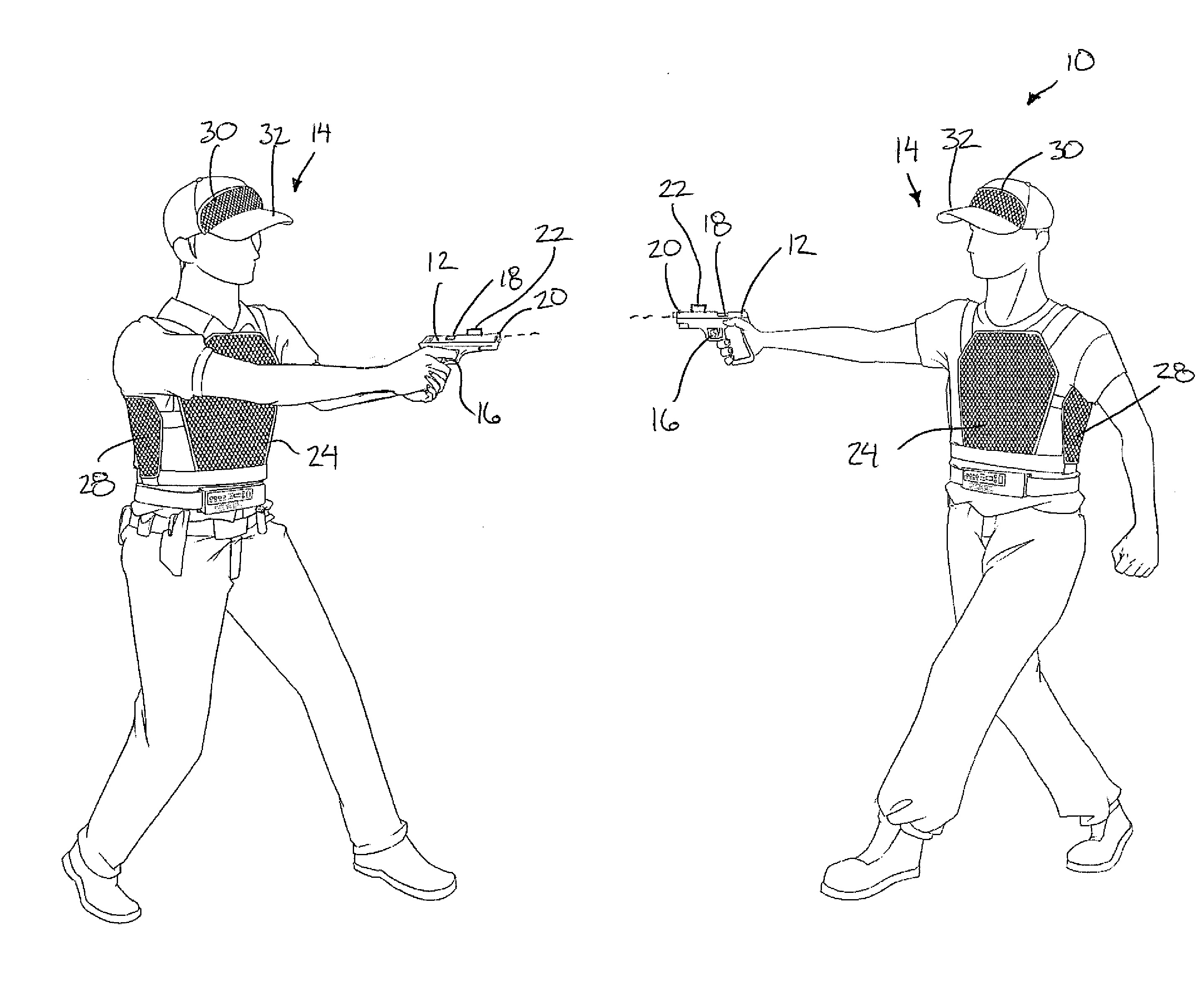
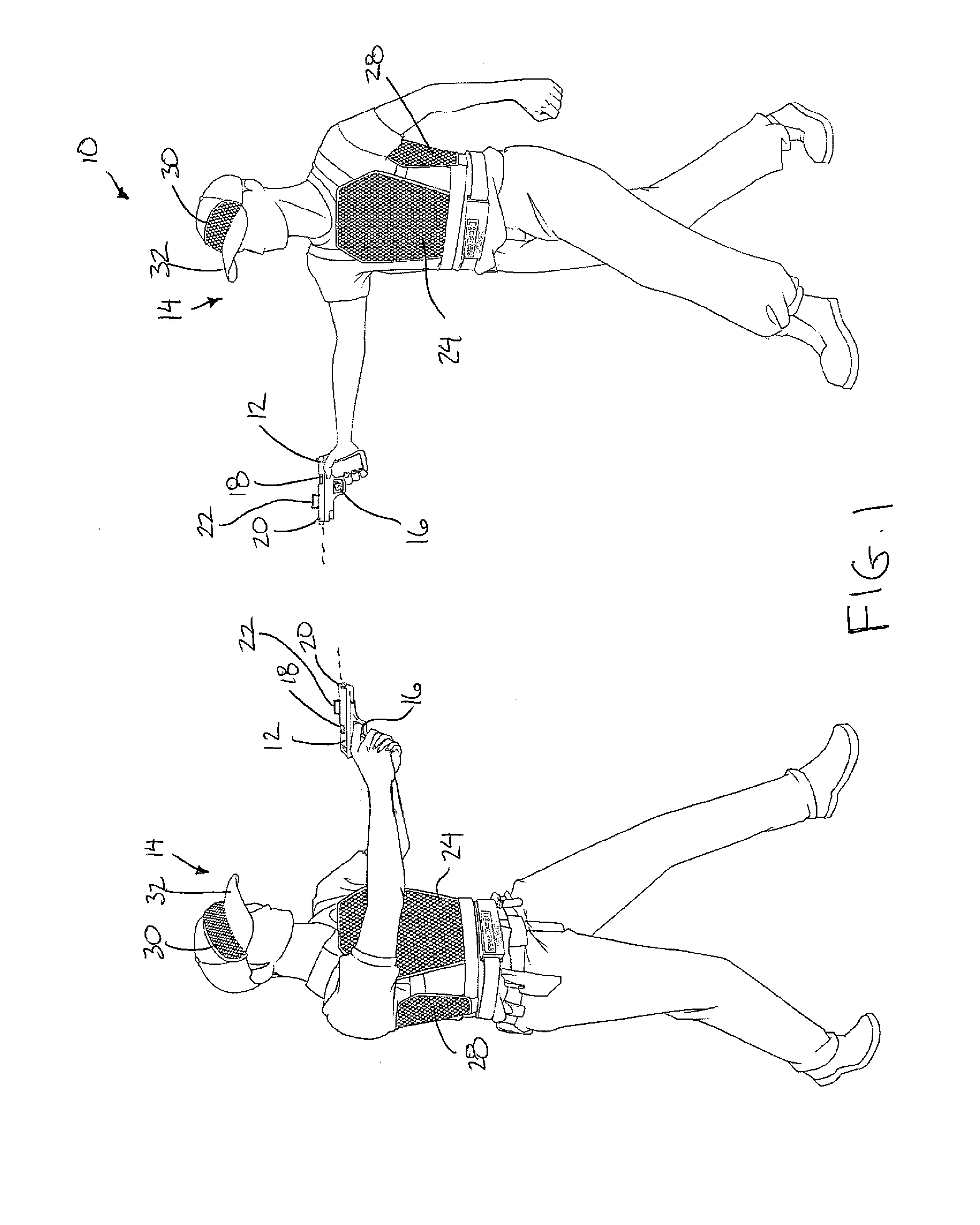
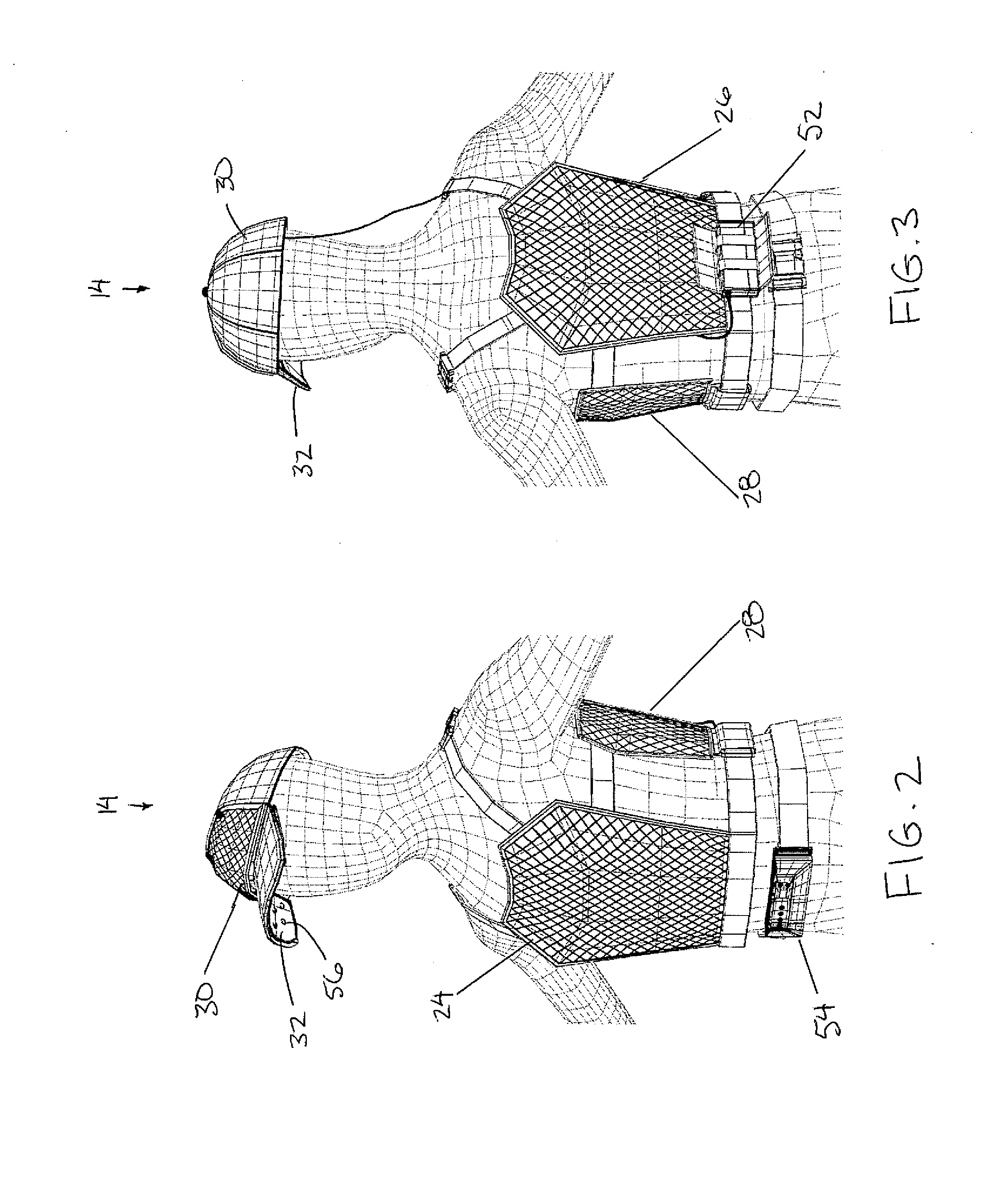
[0041]Referring to the accompanying figures, there is illustrated a light based weapon simulation system generally indicated by reference numeral 10. The system 10 is intended to be used with a plurality of users in which each user is provided with a weapon simulator 12 and a receiver system 14.

[0042]The weapon simulator 12 is generally in the form of a handgun and is used to simulate weapon strikes against other users. The weapon simulator includes a handgun-shaped body carried in the hand of the user and a trigger 16 supported thereon for activation by the user. The weapon simulator further includes a firing chamber 18 arranged to receive a blank cartridge therein and fire the cartridge responsive to actuation of the trigger. A primary transmitter 20 is also provided for emitting a light signal responsive to actuation of the trigger. The light signal generally takes the form of a straight and focused laser beam comprising pulsed light which defines one or more activation codes wit...


PUM


Abstract

A target device is usable with a simulation system which includes a weapon simulator having a trigger, a chamber for firing a blank cartridge in response to the trigger, and a transmitter arranged to emit a light signal defining one or more activation codes of prescribed duration in response to the trigger. The target device includes a sensor array of photodiodes and a processor receiving output signals from the photodiodes. The processor determines that the sensor array has been hit by the weapon simulator in response to a first portion of one activation code being received by one of the photodiodes and at least one second portion of the same activation code being received by the same or a different one of the photodiodes when the first portion and the at least one second portion correspond to an entirety of one activation code within the respective prescribed duration.

Description

FIELD OF THE INVENTION[0001]The present invention relates to a target device arranged to be worn by a user in a weapon simulation system including a simulated weapon arranged to emit a light signal in which the target device is arranged to determine that the user has been hit by the simulated weapon when the light signal is received.BACKGROUND[0002]Various types of combat simulation systems are known for training soldiers and law enforcement officers. For example U.S. Pat. No. 4,487,583 by Brucker et al. discloses a weapons engagement simulation system in which a pulsed beam is generated from a simulated weapon which also incorporates the ability to fire blank charges. Users also wear a vest supporting an array of photodiodes thereon which are arranged to sense the light beam from the weapon directed upon the sensors. A hit is determined only if any single sensor receives an entire activation code within the pulsed beam. As shown in FIG. 7 of Brucker, hits are determined by individu...

Claims


Application Information

Patent Timeline
Patent Type & Authority Applications(United States)
IPC IPC(8): F41G11/00
CPCF41J5/02F41A33/00G09B5/00G09B9/003
Inventor QUAIL, JEFFREY JAMESBOCHINSKI, RORYMCILRAITH, ALEXDRAPER, LUKESWENSEN, FRED
Owner SETCAN CORP
Why Eureka
Try Eureka