
Ultra high resolution gravity gradiometery technique

a gravity gradiometer and high resolution technology, applied in the field of ultra high resolution gravity gradiometery technique, can solve the problem that the resolution limit of the ranging system cannot be used to detect fine human-made underground structures, and achieve the effects of high detection resolution, fast data rate acquisition time, and long integration

Active Publication Date: 2014-07-10
CALIFORNIA INST OF TECH
View PDF4 Cites 11 Cited by
  • Summary
  • Abstract
  • Description
  • Claims
  • Application Information

AI Technical Summary

Benefits of technology

The present invention provides a system and method to detect changes in the gravity field caused by subterranean structures with high precision and at a faster data acquisition time compared to existing systems. The detection resolution is achieved by integrating over a shorter period of time, allowing for a smaller separation distance between the satellites. The invention also eliminates the need for a long integration time to reduce statistical error and collect a large number of data points.

Problems solved by technology

Also the resolution limit of their ranging system doesn't allow them to detect fine human made underground structures.

Method used


Image

  • Ultra high resolution gravity gradiometery technique
  • Ultra high resolution gravity gradiometery technique
  • Ultra high resolution gravity gradiometery technique

Examples


Embodiment Construction

[0034]In the following description, reference is made to the accompanying drawings which form a part hereof, and which is shown, by way of illustration, several embodiments of the present invention. It is understood that other embodiments may be utilized and structural changes may be made without departing from the scope of the present invention.

Qualitative Description

[0035]To understand embodiments of the invention, a qualitative description is useful, followed by a the derivation of an analytical expression.

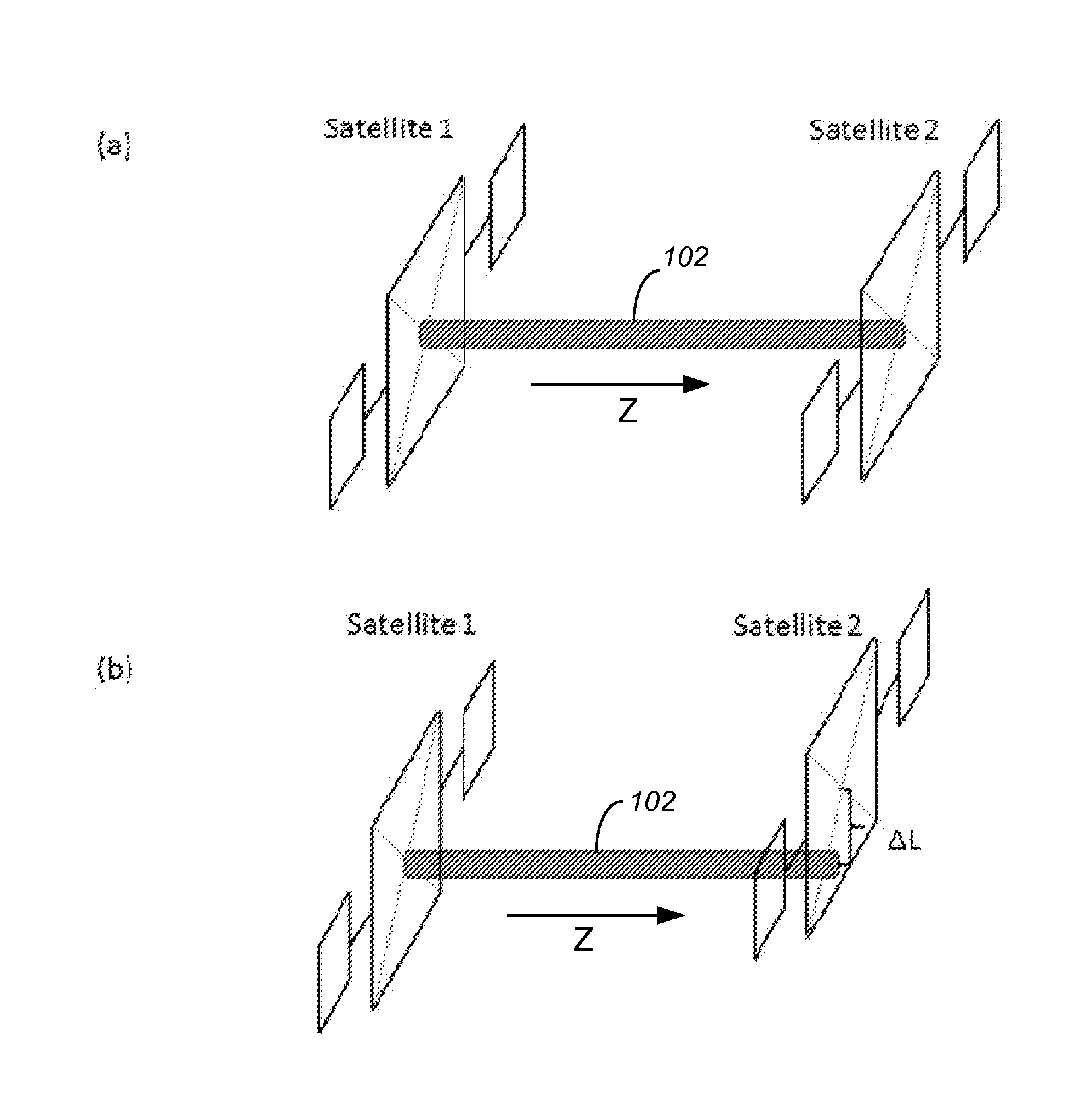
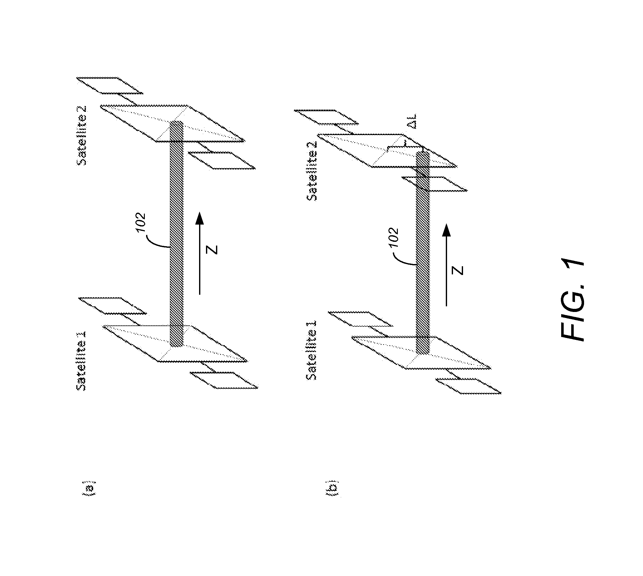
[0036]One may assume the existence of two satellites and it is desirable to measure their relative displacement by monitoring the displacement of a beam of light located on one of the satellites and shining to a plate fixed to the other satellite. FIGS. 1(a) and 1(b) illustrate the general concept of shining light between two satellites and measuring a relative displacement in accordance with one or more embodiments of the invention. Assume that the light source is located on s...


PUM


Abstract

A method and system provide the ability to measure relative displacement and rotation. A first light is continuously shined from a first light source that is fixed on a first entity to a first two-dimensional (2D) plate fixed on a second entity. The first direction of propagation of the first light does not change relative to the first entity. A second light is shined from a second light source that is fixed on the first entity to a second 2D plate fixed on the second entity. A second direction of propagation of the second light does not change relative to the first entity and is different from the first direction of propagation. The displacement of the lights on plates is directly monitored to determine a 3D displacement vector that represents a relative displacement between the first entity and the second entity. Thus, a three dimensional gravity gradient tensor is constructed.

Description

CROSS-REFERENCE TO RELATED APPLICATIONS[0001]This application claims the benefit under 35 U.S.C. Section 119(e) of the following co-pending and commonly-assigned U.S. provisional patent application(s), which is / are incorporated by reference herein:[0002]Provisional Application Ser. No. 61 / 579,573, filed on Dec. 22, 2011, by Shervin Taghavi, entitled “Novel remote sensing technique based on measuring the relative displacement between two satellites,” attorneys' docket number 176.76-US-P2; Provisional Application Ser. No. 61 / 619,290, filed on Apr. 2, 2012, by Shervin Taghavi, Massimo Tinto, Jakob J. VanZyl, Michael R. Hoffmann, and Christopher Boxe, entitled “Novel remote sensing technique based on measuring the relative displacement between two satellites,” attorneys' docket number 176.76-US-P3; and[0003]Provisional Application Ser. No. 61 / 665,793, filed on Jun. 28, 2012, by Shervin Taghavi, Jakob J. VanZyl, Michael R. Hoffmann, and Christopher Boxe, entitled “Novel Remote Sensing Te...

Claims


Application Information

Patent Timeline
Patent Type & Authority Applications(United States)
IPC IPC(8): G01V7/04G01B11/14
CPCG01B11/14G01V7/04G01S11/12
Inventor LARIGANI, SHERVIN TAGHAVI
Owner CALIFORNIA INST OF TECH
Learn More