
Imaging apparatus, signal processing method, and program

a signal processing and imager technology, applied in the field of imagers, can solve the problems of overexposure of pixels, insufficient exposure time in the dark portion, and the upper limit of charge accumulation in the photoelectric conversion element, and achieve the effect of short time exposure of pixels and long time exposure pixels

Active Publication Date: 2014-07-10
SONY SEMICON SOLUTIONS CORP
View PDF5 Cites 42 Cited by
  • Summary
  • Abstract
  • Description
  • Claims
  • Application Information

AI Technical Summary

Benefits of technology

This patent describes an apparatus and method for creating a wide dynamic range image by combining two different exposure time pixels. The method involves performing control of different exposure times for each pixel in a pixel block and adding the outputs of the pixels to generate an addition pixel value. This is done using an operation unit with an adding unit or a floating diffusion set in a pixel block unit. The technical effect of this invention is the ability to produce a high dynamic range image with improved dynamic range and color accuracy.

Problems solved by technology

However, there is an upper limit in a charge accumulation amount in a photoelectric conversion element.
However, if the shutter is released fast in imaging of a subject in which a bright place and a dark place are mixed, a sufficient exposure time is not taken in a dark portion.
As a result, pixels may become overexposure pixels.
However, the following problems occur in the process based on the plurality of images.
Problem 2: because a plurality of images of which imaging timings are different are combined or imaging data of long time exposure is used, camera shaking is easily generated.
However, in the configurations described above, noise is likely to be generated due to manufacturing variations of elements or filters and it is difficult to acquire an image of a high quality.

Method used


Image

  • Imaging apparatus, signal processing method, and program
  • Imaging apparatus, signal processing method, and program
  • Imaging apparatus, signal processing method, and program

Examples


Embodiment Construction

[0052]Hereinafter, an imaging apparatus, a signal processing method, and a program according to the present disclosure will be described in detail with reference to the drawings. The description is made according to the following items.

1. With respect to configuration example of pixel unit of imaging device

2. With respect to a configuration example of imaging apparatus

3. With respect to configuration example of imaging device

4. With respect to exposure time control configuration of pixel unit and calculation process example of output pixel value

5. With respect to specific circuit configuration example of imaging device

6. Floating diffusion (FD) addition configuration example

7. With respect to other embodiments

8. Summary of configuration according to present disclosure

[1. With Respect to Configuration Example of Pixel Unit of Imaging Device]

[0053]A configuration example of a pixel unit of an imaging device to be a component of an imaging apparatus according to the present disclosure ...


PUM


Abstract

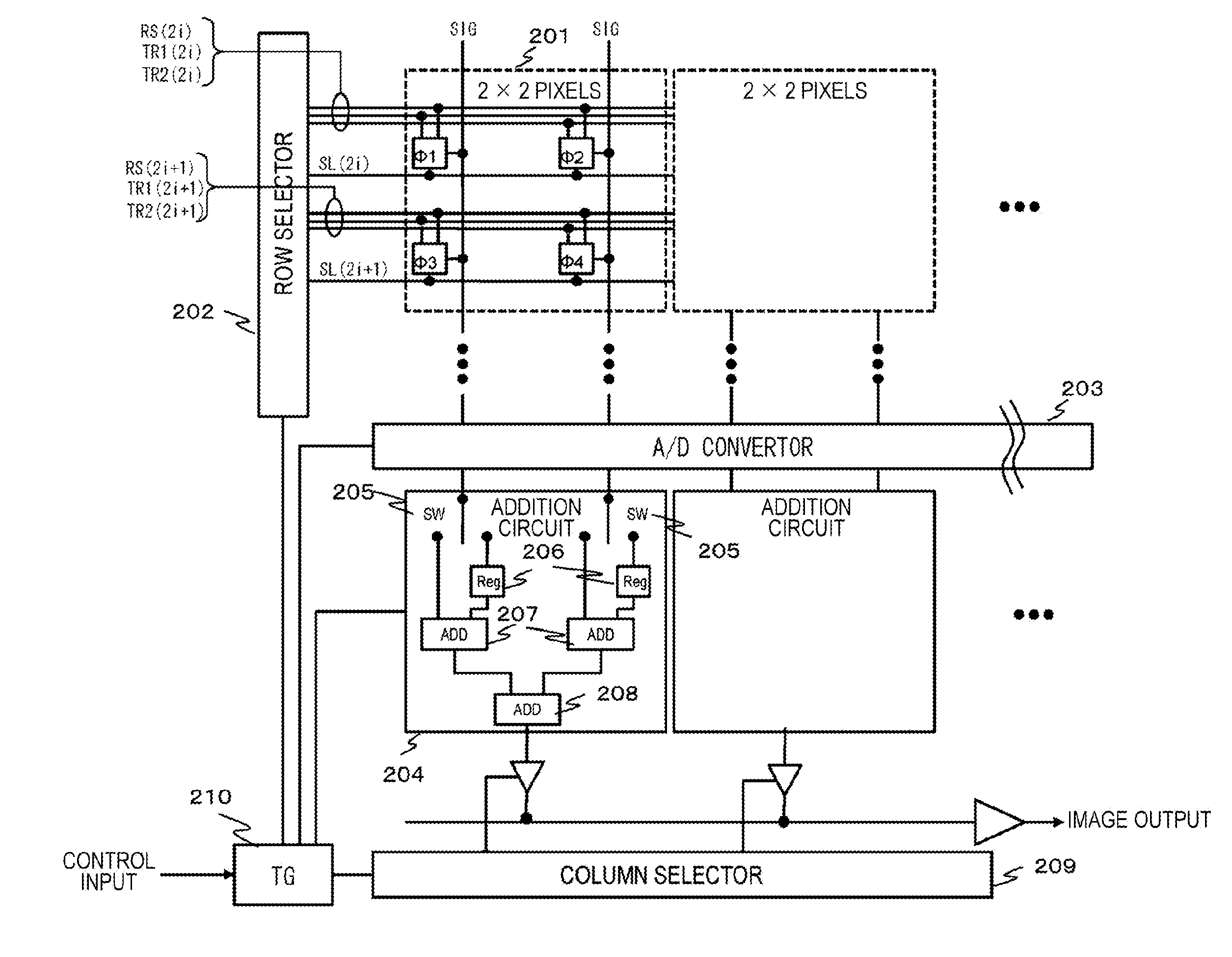
The present disclosure provides an apparatus and a method for generating a wide dynamic range image by executing a pixel value combination process of a plurality of different exposure time setting pixels. Control of a different exposure time is performed for each of a plurality of pixels of the same colors configuring a pixel block and an addition pixel value obtained by adding outputs of the plurality of pixels of the same colors of the pixel block is generated. The generation of the addition pixel value is executed in an operation unit having an adding unit that that adds the outputs of the plurality of pixels of the same colors of the pixel block. Or, the generation of the addition pixel value is executed by a floating diffusion (FD) set in a pixel block unit and a charge output from each of the plurality of pixels of the same colors configuring the pixel block is accumulated and output in the floating diffusion (FD).

Description

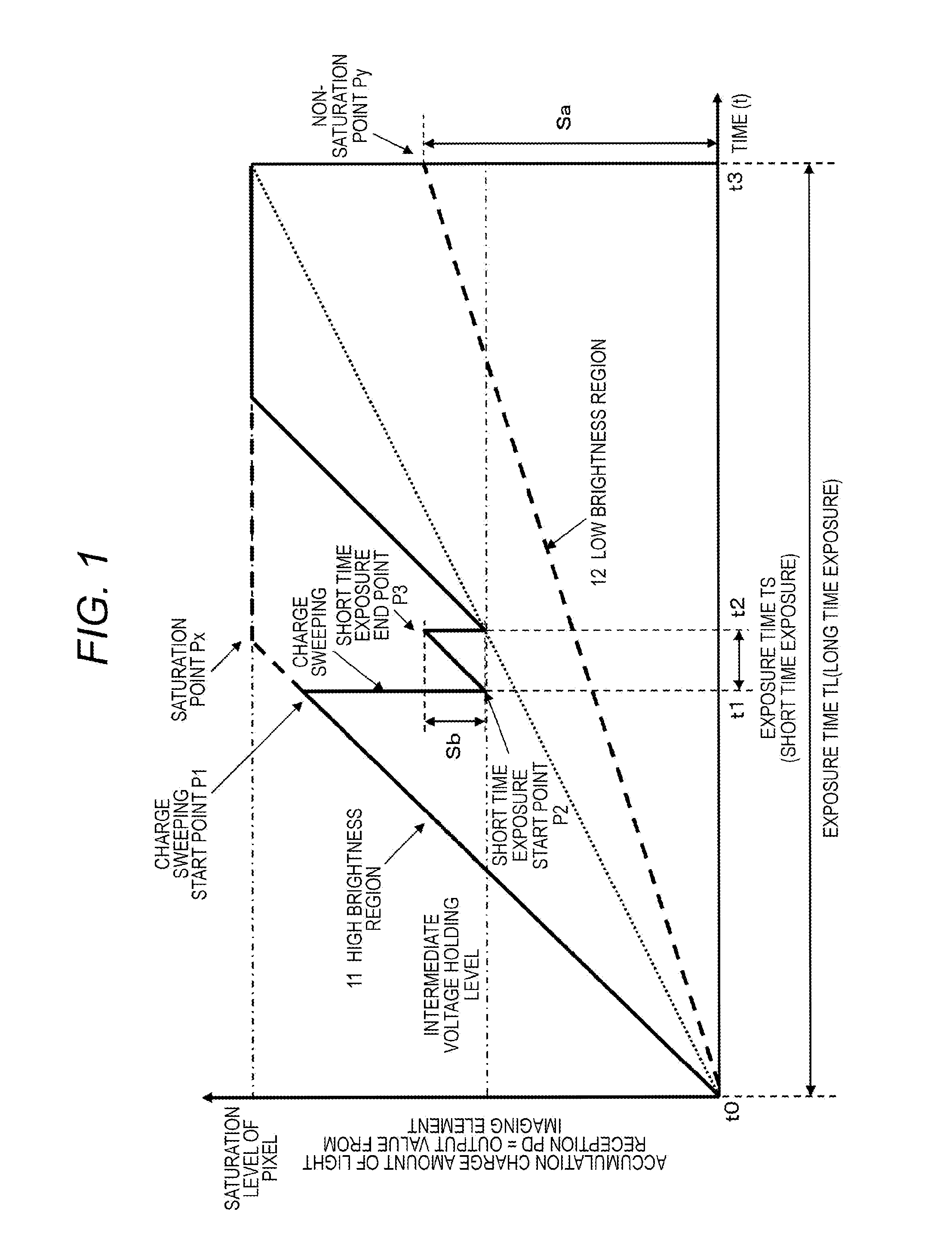
TECHNICAL FIELD[0001]The present disclosure relates to an imaging apparatus, a signal processing method, and a program. In detail, the present disclosure relates to an imaging apparatus, a signal processing method, and a program that enable an image of a wide dynamic range to be generated.BACKGROUND ART[0002]Solid-state imaging devices such as a CCD image sensor or a complementary metal oxide semiconductor (CMOS) image sensor that are used in a video camera or a digital still camera perform photoelectric conversion for accumulating a charge according to an amount of incident light and outputting an electric signal corresponding to the accumulated charge. However, there is an upper limit in a charge accumulation amount in a photoelectric conversion element. If light of an amount equal to or more than a constant amount is received, so-called overexposure in which an accumulation charge amount reaches a saturation level and a brightness level of a subject region of constant brightness ...

Claims


Application Information

Patent Timeline
Patent Type & Authority Applications(United States)
IPC IPC(8): H04N9/04H04N5/235H04N25/46H04N23/12H04N23/75H04N23/76H04N25/00
CPCH04N5/2355H04N5/37457H04N9/045H04N5/35554H04N5/3535H04N5/2353H04N23/73H04N23/741H04N25/533H04N25/583H04N25/70H04N25/778H04N25/133H04N25/134H04N25/76
Inventor MITSUNAGA, TOMOO
Owner SONY SEMICON SOLUTIONS CORP
Learn More