Indirectly heated gas turbine system

a gas turbine and indirect heating technology, applied in steam engine plants, air transportation, climate sustainability, etc., can solve the problems of small gas turbines, so-called micro-turbines, low efficiency, increase energy losses, etc., and achieve high efficiency

Active Publication Date: 2013-10-17
MASTON
View PDF1 Cites 3 Cited by
  • Summary
  • Abstract
  • Description
  • Claims
  • Application Information

AI Technical Summary

Benefits of technology

[0016]The object of the present invention is to provide a compact, indirectly heated gas turbine system having high efficiency, which can be used for the operation of, for instance, vehicles by biomass fuel in solid form.
[0018]By integration of the heat exchanger and the combustion chamber in a monolithic unit, the heat losses in the passage of the flue gas from the combustion chamber to the heat exchanger can be efficiently decreased. The system utilises both radiant heat from the combustion chamber and convection heat in the first heat exchanger device in the heating of the working medium. In such a way, an increased input temperature of the working medium at the inlet to the turbine can be achieved.
[0019]Likewise, a considerable decrease of the volume of the gas turbine system can be provided, which allows incorporation in, for instance, a vehicle, such as a private car or the like.
[0023]In a further advantageous embodiment, the first heat exchanger device comprises a heat transfer passage for the working medium of the turbine in the form of a helical channel running substantially tangentially around the circumference of the combustion chamber. The helical shape facilitates heat transfer to the working medium, both from the combustion chamber and the flue gas.
[0025]In yet another preferred embodiment, the second heat exchanger device comprises a swirl chamber having a heat transfer surface that faces away from the combustion chamber, designed such that the working medium skims the heat transfer surface several times before the working medium exits into the turbine. With longer exposure to the heat transfer surface, a higher temperature and a more even temperature distribution in the working medium is achieved.

Problems solved by technology

Smaller gas turbines, so-called micro turbines, usually have low efficiency, while gas turbines of the size 1 MW and above achieve higher efficiency, however never comparable to the one of piston engines.
However, because of energy losses through the compressor and the turbine of a real gas turbine, these processes are adiabatic.
Also biomass fuels in solid form, such as wood pellets, reed, straw or grass have been targeted as candidates, but are associated with the disadvantage that the flue gas and the combustion products from the combustion chamber may cause fouling and contamination of the turbine blades when passing the turbine step, which may increase the energy losses and thereby lower the efficiency of the gas turbine.
The turbine blades also risk being exposed to chemical attack in the form of corrosion, depending on which fuel is used.
A disadvantage of the known technique is that it often has a low efficiency because of energy losses in the gas turbine system along the path followed by the working medium and / or of the flue gas from the compressor via the combustion chamber and the heat exchanger to the turbine, which contributes to lower the efficiency.
One disadvantage of this type of construction is that it requires a relatively large space, something which prevents integration into, for example, vehicles of the private car type or other systems having requirements of compactness.
Another drawback is that the heat exchanger must be cleaned at regular intervals to remove byproducts from combustion, such as soot or carbonaceous deposits.

Method used


Image

  • Indirectly heated gas turbine system
  • Indirectly heated gas turbine system
  • Indirectly heated gas turbine system

Examples


Embodiment Construction

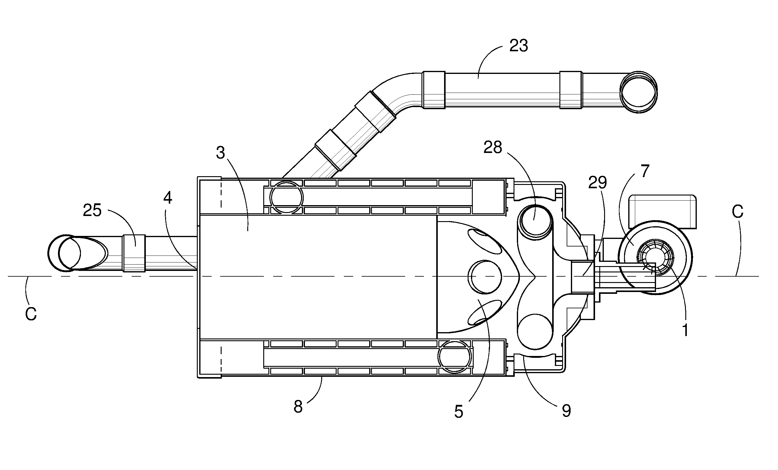
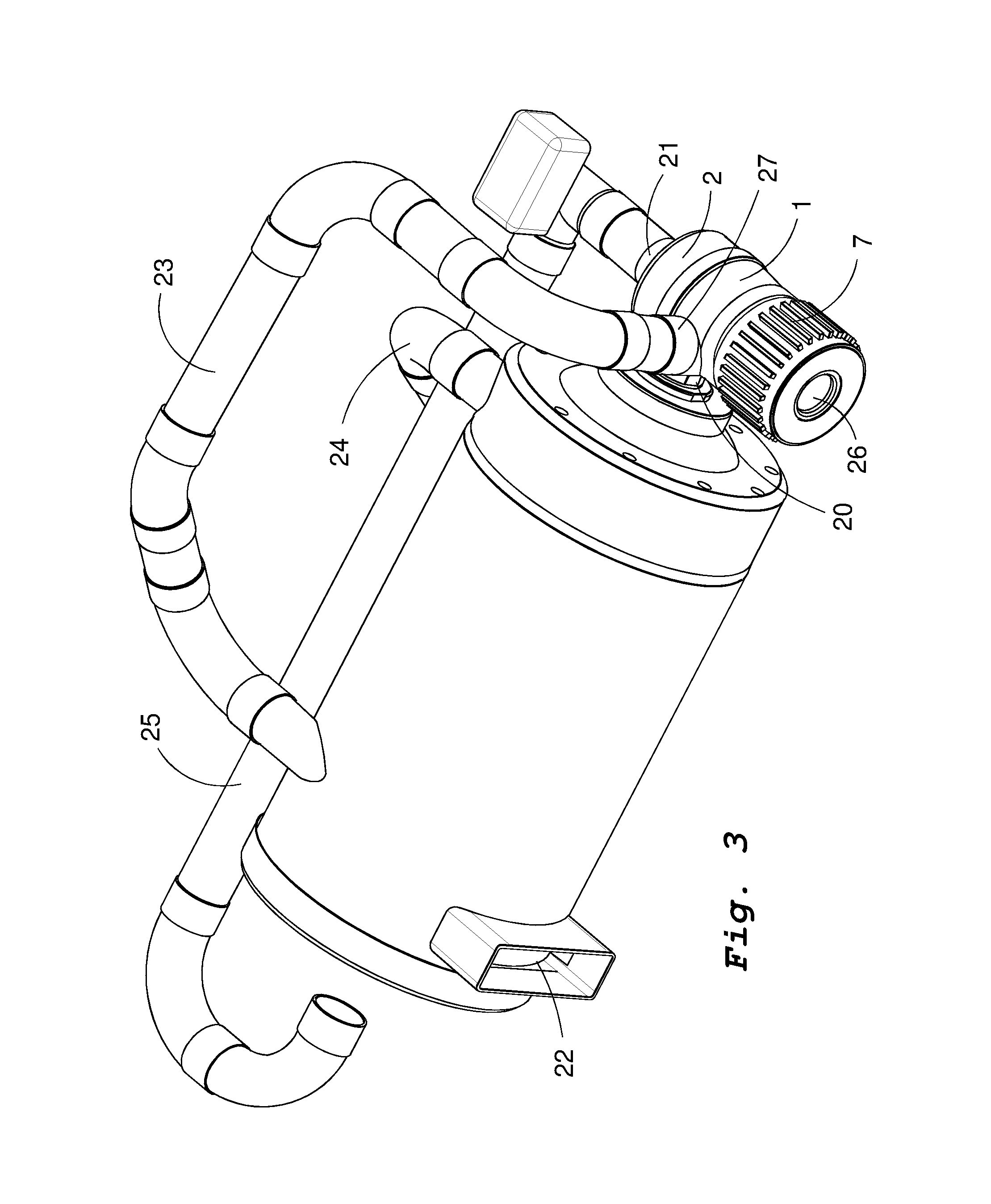
[0037]The gas turbine system will be described below more in detail, reference being made to the fig.s. However, the invention should not be considered limited to the embodiment or embodiments shown in the fig.s and described below, but may be varied within the scope of the claims.

[0038]In the present disclosure the term ‘monolithic unit’ should be interpreted as meaning a unit formed to constitute one piece, which may not be taken apart or in other ways disassembled, unless explicitly stated otherwise.

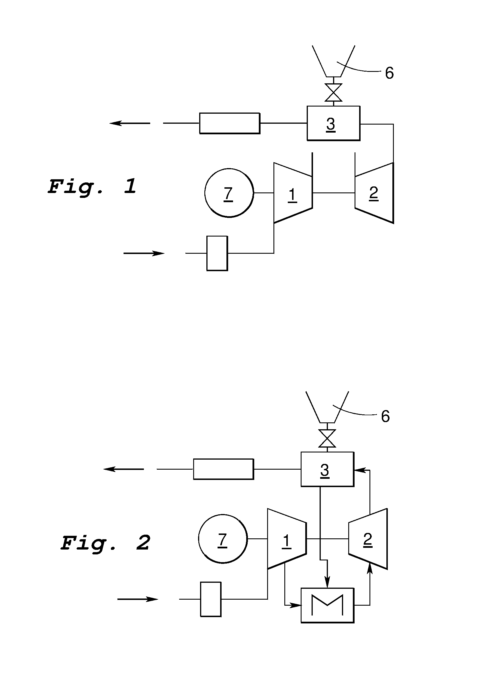
[0039]Generally, for all types of heat engines, which convert thermal energy (heat) to mechanical energy (work), the efficiency η is defined as the ratio between extracted work, W, and supplied amount of heat, Q:

η=WQ

[0040]Since a real heat engine is limited because of energy losses, the entire supplied amount of heat cannot be converted into work, but a certain amount is dissipated to the surroundings as waste heat:

Qin=W+Qut

[0041]The efficiency will then be:

η=Qin-QoutQin=1-QutQin

[004...


PUM


Abstract

The present invention relates to an indirectly heated gas turbine system comprising a combustion chamber (3) that extends along a central axis of the gas turbine system for the combustion of compressed air and supplied fuel whereby flue gas is formed, a turbine (2) driven by a working medium, a compressor (1) rotatably connected to the turbine for compressing the working medium and / or air to the combustion chamber, and a first heat exchanger device (8) for the transfer of heat between the flue gas and the working medium. The first heat exchanger device and the combustion chamber are integrally formed as a monolithic unit, the first heat exchanger device being substantially arranged within the axial extension of the combustion chamber along the central axis. By the integrated design of the combustion chamber and the first heat exchanger device, a compact, indirectly heated gas turbine system having high efficiency is achieved.

Description

[0001]The present invention relates to an indirectly heated gas turbine system comprising a combustion chamber for the combustion of compressed air and supplied fuel whereby flue gas is formed, a turbine driven by a working medium, a compressor rotatably connected to the turbine for compressing the working medium and / or air to the combustion chamber, and a first heat exchanger device for the transfer of heat between the flue gas and the working medium.TECHNICAL BACKGROUND OF THE INVENTION[0002]A gas turbine is a turbine driven by flowing combustion gases from a combustion chamber, which is the proper source of power. Accordingly, a gas turbine is the same thing as a jet engine where the gases, instead of flowing out into a jet, are allowed to drive a turbine rotatably connected to, for instance, an electric generator. Therefore, a usual field of application for the gas turbine is electric power generation.[0003]Gas turbines have very high power in relation to their size and weight a...

Claims


Application Information

Patent Timeline
Patent Type & Authority Applications(United States)
IPC IPC(8): F02C1/05
CPCF02C1/05F02C1/04F05D2250/82F02C1/06F02C1/10Y02T50/60
Inventor LARSSON, STEFANLINDSTROM, ANDERSKOBES, HANSI
Owner MASTON
Why Eureka
Try Eureka