Environmental barrier coating for silicon-containing substrates and process therefor

a technology of environmental barrier coating and silicon-containing substrate, which is applied in the field of coating systems, can solve problems such as degradation of environmental protective properties of coating, and achieve the effects of improving volatilization resistance, increasing recession rate, and improving performance in corrosive environments

Inactive Publication Date: 2007-08-09
GENERAL ELECTRIC CO
View PDF4 Cites 2 Cited by
  • Summary
  • Abstract
  • Description
  • Claims
  • Application Information

AI Technical Summary

Benefits of technology

[0010] SAS protective coatings of this invention are believed to be capable of withstanding higher temperatures and / or longer exposures to the combustion environment within a gas turbine engine as a result of the substantial absence of the second phase, whose susceptibility to volatilization leads to coating recession. The protective coatings of this invention are also believed to be more resistant to corrosive environments (e.g., sea salt) and CMAS-containing environments, which also lead to severe degradation and increased recession rates of BSAS coatings of the prior art. As such, the SAS protective coatings of this invention are able to exhibit improved performance in corrosive environments and exhibit increased volatilization resistance at temperatures above 2300° F. (about 1260° C.) while subjected to high gas velocities, enabling the coatings to be used in more demanding aircraft engine applications such as vanes, blades, shrouds, and combustors.

Problems solved by technology

(about 1260° C.) combined with high pressure steam and high gas velocities) have resulted in the volatilization of existing BSAS materials, causing coating recession that ultimately leads to degradation of the environmental protective properties of the coating.

Method used


Image

  • Environmental barrier coating for silicon-containing substrates and process therefor
  • Environmental barrier coating for silicon-containing substrates and process therefor
  • Environmental barrier coating for silicon-containing substrates and process therefor

Examples


Embodiment Construction

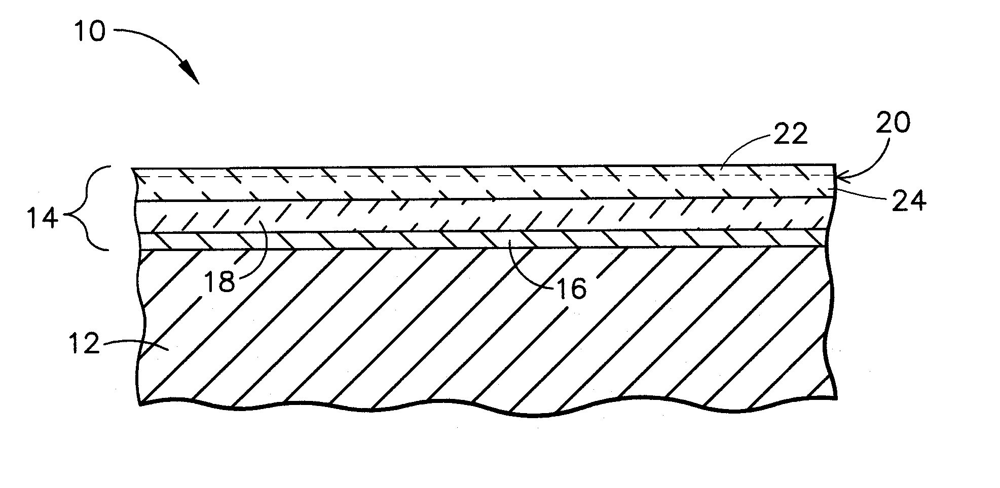
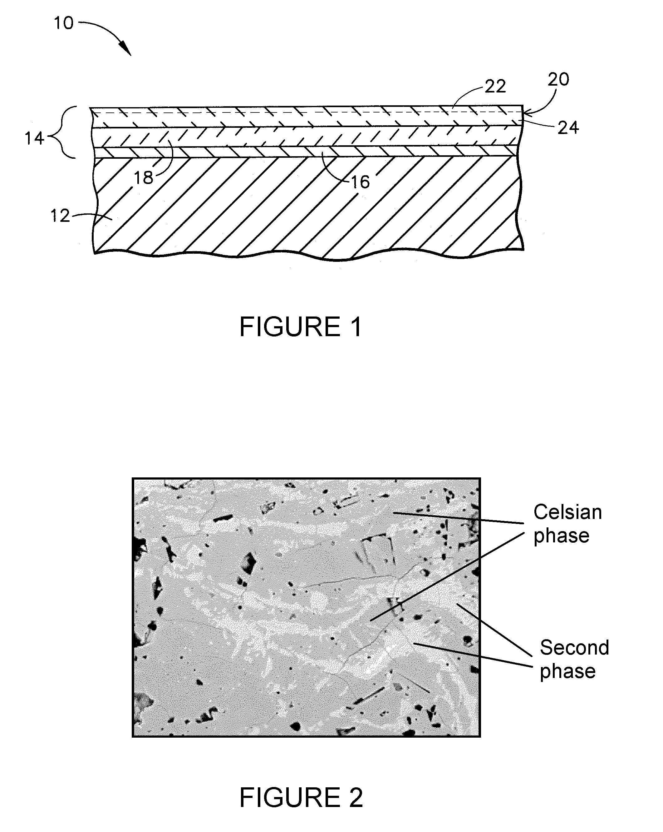
[0018] The present invention is directed to a coating composition for an environmental barrier coating system suitable for protecting silicon-containing components subjected to high temperatures in the presence of water (water vapor) and corrosive agents, including the high and low pressure turbine vanes (nozzles) and blades (buckets), shrouds, combustor liners and augmentor hardware of gas turbine engines. Examples of silicon-containing materials for such applications include monolithic materials (e.g., silicon carbide, silicon nitride, etc.), composite materials containing a dispersion of silicon carbide, silicon nitride, and / or silicon reinforcement material in a metallic or nonmetallic matrix, composite materials having a silicon carbide, silicon nitride and / or silicon-containing matrix, and composite materials that employ silicon carbide, silicon nitride and / or silicon as both the reinforcement and matrix materials (e.g., SiC / SiC ceramic matrix composites (CMC)). While the adva...


PUM

PropertyMeasurementUnit
temperaturesaaaaaaaaaa
thicknessaaaaaaaaaa
temperaturesaaaaaaaaaa

Abstract

A protective coating for use on a silicon-containing substrate, and deposition methods therefor. The coating has a strontium-aluminosilicate (SAS) composition that is less susceptible to degradation by volatilization and in corrosive environments as a result of having at least an outer surface region that consists essentially of one or more stoichiometric crystalline phases of SAS and is substantially free of a nonstoichiometric second crystalline phase of SAS that contains a substoichiometric amount of silica. The coating can be produced by carrying out deposition and heat treatment steps that result in the entire coating or just the outer surface region of the coating consisting essentially of the stoichiometric celsian phase.

Description

CROSS REFERENCE TO RELATED APPLICATIONS [0001] This is a continuation-in-part patent application of co-pending U.S. patent application Ser. No. 10 / 709,288, filed Apr. 27, 2004, the contents of which are incorporated herein by reference.BACKGROUND OF THE INVENTION [0002] This invention relates to coating systems suitable for protecting components exposed to high-temperature environments, such as the hot gas flow path through a gas turbine engine. More particularly, this invention is directed to a coating composition that exhibits improved high temperature stability when used to protect a silicon-containing substrate. [0003] Higher operating temperatures for gas turbine engines are continuously sought in order to increase their efficiency. While nickel, cobalt and iron-base superalloys have found wide use for components throughout gas turbine engines, alternative materials have been proposed. In particular, silicon-based non-oxide ceramics, most notably with silicon carbide (SiC) as a...

Claims


Application Information

Patent Timeline
Patent Type & Authority Applications(United States)
IPC IPC(8): B32B13/04B05D3/02C04B41/50F01D5/28F23R3/00
CPCC04B35/195F05D2300/2112C04B41/5024C04B41/52C04B41/85C04B41/89C04B2235/3213C04B2235/3215C04B2235/3217C04B2235/3481C04B2235/79C04B2235/80C23C4/105C23C4/18C23C30/00F01D5/288F23M2900/05004F23R3/007Y02T50/67Y02T50/672C04B41/009F05D2300/211F05D2230/90C23C28/04C04B41/4527C04B41/5096C04B41/5037C04B41/5042C04B35/565C04B35/584C04B35/806C04B41/0072C04B41/4519C04B2111/0025C23C4/11Y02T50/60
Inventor HAZEL, BRIAN THOMASWALSTON, CHRISTINESPITSBERG, IRENE
Owner GENERAL ELECTRIC CO
Why Eureka
Try Eureka