Method and Apparatus for Shaping Dynamic Light Beams to Produce 3D Perception in a Transmitted Light Microscope

a technology of transmitted light and beams, which is applied in the field of transmitted light microscope illuminator, can solve the problems of mechanical moving parts, special lenses, prisms and apertures that are expensive and difficult to implement, and require the replacement of microscope parts

Inactive Publication Date: 2014-07-10
EDGE 3D
View PDF3 Cites 8 Cited by
  • Summary
  • Abstract
  • Description
  • Claims
  • Application Information

AI Technical Summary

Benefits of technology

[0004]Another advantage of the present invention over the prior art is that it does not sacrifice light intensity by blocking any portion of the aperture, as do prior art LCD shutter systems. In addition, LCD shutters polarize the light, and polarized light is not compatible with some optical modalities, such as polarization microscopy or Nomarski optics. The illumination system of the present invention is compatible with all such systems, since no light polarization takes place in order to produce 3D images.
[0005]The light source has a strategic position in the optical path of a light microscope because it can be made optically conjugate to the pupil (or aperture) of the objective lens, known as Koehler illumination. The novel illuminator of the present invention comprises an array of individual light sources (lighting elements) that are positioned to replace a standard bulb in a light microscope. In this position, each small lighting element illuminates only a portion of the aperture of the optical system. Each lighting element can be individually controlled to be either turned on or off, have a selected lumen output (intensity), and turned on for a selected duration. This arrangement allows a user to

Problems solved by technology

Other systems require mechanical moving parts, special lenses, prisms and apertures that are expensive and difficult to implement and require that parts of the microscope be rebuilt.
The same problems occur with systems tha

Method used


Image

  • Method and Apparatus for Shaping Dynamic Light Beams to Produce 3D Perception in a Transmitted Light Microscope
  • Method and Apparatus for Shaping Dynamic Light Beams to Produce 3D Perception in a Transmitted Light Microscope
  • Method and Apparatus for Shaping Dynamic Light Beams to Produce 3D Perception in a Transmitted Light Microscope

Examples


Embodiment Construction

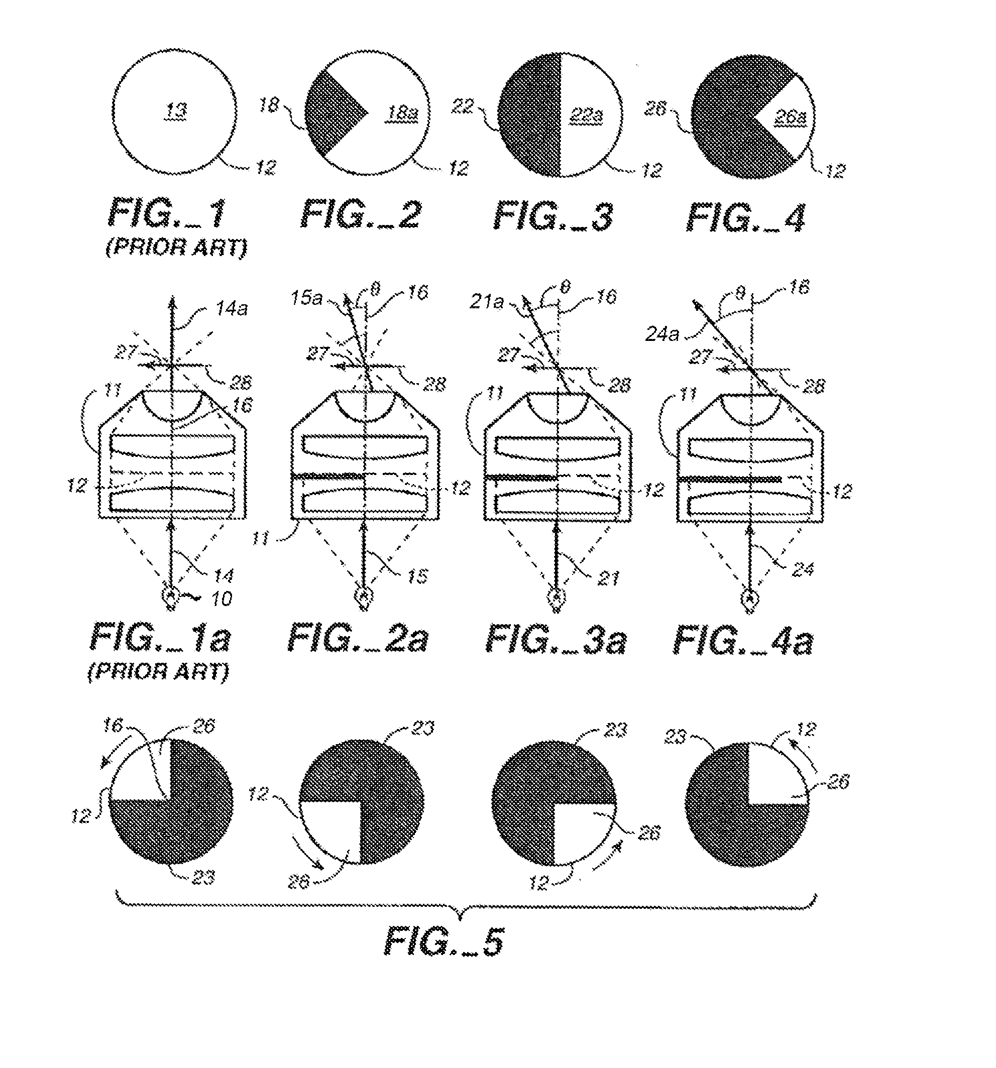
[0031]Referring to FIGS. 1 and 1a (Prior Art), a typical prior art transmitted light microscope (not all parts of which are shown) has a condenser lens 11 with an aperture 12 (shown in plan view in FIG. 1) having an area 13. The microscope illumination is provided by a light bulb 10 which, when emitting light, provides a light beam 14 along the microscope's optical axis 16 that enters the condenser lens 11 passing through its aperture 12 and exiting along an optical axis 14a that, in this case, coincides with the microscope's optical axis 16. There being no non-concentric shaping of the beam 14, the entire area 13 of aperture 12 is typically filled with the light from beam 14, as indicated by the area 13 being all white (unless otherwise indicated, white connotes an area that is illuminated and black connotes an area that is not illuminated or “dark”).

[0032]As more fully described below, in reference to the present invention, a light beam is considered “shaped” when it non-concentri...


PUM


Abstract

An illuminator for a transmitted light microscope for producing stereo viewing as well as motion parallax 3D perception, using a generally pyramid-shaped mirror having a plurality of facets and light source adjacent a plurality of the facets and a computer-driven electronic circuit for controlling the on/off status of said light sources.

Description

FIELD OF THE INVENTION[0001]The present invention relates to a transmitted light microscope illuminator and, more specifically, to methods and apparatus by which an illuminator for an otherwise 2D transmitted light microscope enhances the microscope's capabilities to include stereo 3D and motion parallax 3D perception.BACKGROUND OF THE RELATED ART[0002]In my U.S. Pat. No. 6,891,671, I teach that by physically obscuring successive portions of the aperture of a light microscope, stereo 3D and motion parallax 3D perception can be achieved. The present invention is an improved 3D imaging system that employs a unique illumination system (illuminator) that produces and deploys a shaped light beam to create motion parallax.SUMMARY OF THE INVENTION[0003]The novel lighting system and methods of the present invention produces shaped light beams controlled by a computer having a functional graphical user interface (GUI). There are a number of advantages to the present invention over the prior ...

Claims


Application Information

Patent Timeline
IPC IPC(8): G02B21/08G02B21/06
CPCG02B21/06G02B21/086G02B5/09G02B21/22
Inventor GREENBERG, GARY
Owner EDGE 3D
Why Eureka
Try Eureka