Assembly comprising a radially intermediate joint

Inactive Publication Date: 2014-07-10
SKF BV
View PDF1 Cites 1 Cited by
  • Summary
  • Abstract
  • Description
  • Claims
  • Application Information

AI Technical Summary

Benefits of technology

The patent text describes an intermediate joint that is stronger and more functional than existing joints. The joint has two parts that can be easily manufactured and adapted for different applications. The first part is made of a high-strength metal material, while the second part is made of a filler material that can be welded or brazed to the first and second surfaces. The joint also has a radial gap that is sealed by an insert ring to ensure the components are locked together securely. Overall, the patent text describes a joint design that has improved strength and performance capabilities.

Problems solved by technology

However, the machining of a toothed profile into each connecting surface adds to the complexity and cost of the manufacturing process.

Method used


Image

  • Assembly comprising a radially intermediate joint
  • Assembly comprising a radially intermediate joint
  • Assembly comprising a radially intermediate joint

Examples


Embodiment Construction

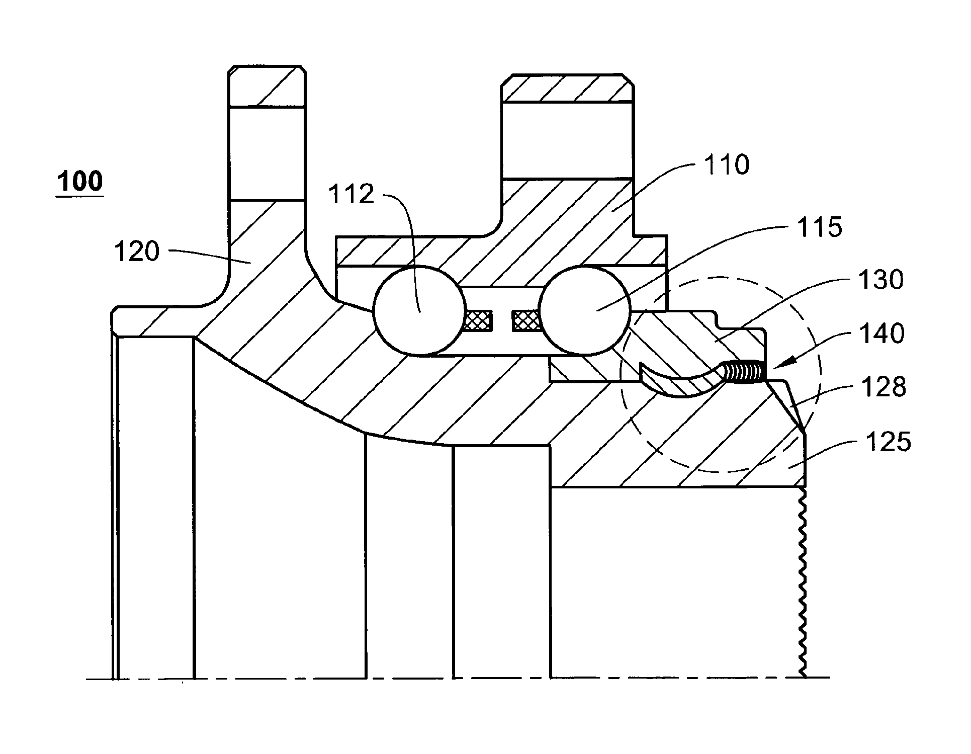
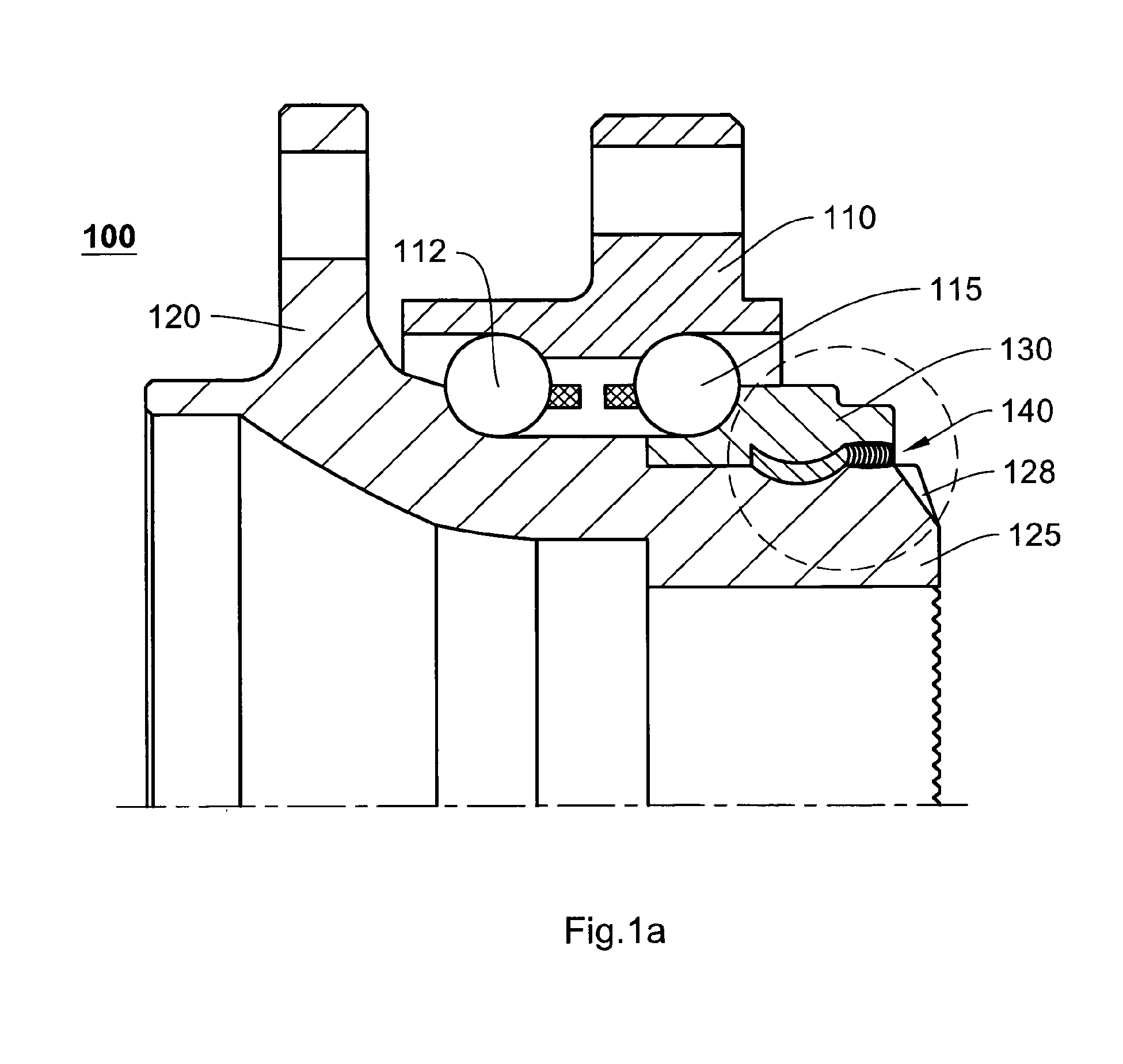
[0030]An example of an assembly according to the invention is shown in cross-section in FIG. 1a. The assembly is part of a wheel bearing unit 100 having an outer ring 110 with first and second outer raceways for accommodating a first row 112 and a second row 115 of rolling elements. The bearing unit further comprises a flanged inner ring 120 which has a first inner raceway for the first row of rolling elements 112. The second inner raceway for the second row of rolling elements 115 is provided on a separate inner ring 130. The separate inner ring is necessary in order to allow the second row of rolling elements to be inserted into the hub unit 115 after the outer ring 110 has been mounted over the first row 112. The separate inner ring 130 is mounted on a nose part 125 of the flanged inner ring 120. In conventional hub units, the nose part comprises an axial extension, which is orbitally formed around the separate inner ring, to lock up the bearing unit and set the desired amount of...


PUM

PropertyMeasurementUnit
Thicknessaaaaaaaaaa
Volumeaaaaaaaaaa
Strengthaaaaaaaaaa

Abstract

The present invention resides in an assembly comprising a first component (130) joined to a second component (120) by means of an intermediate joint. The first component has a first joining surface arranged coaxially and in spaced juxtaposition around a second joining surface of the second component, such that a radial gap is defined between the first and second joining surfaces. Furthermore, at least one of the first and second joining surfaces comprises a circumferential groove. The intermediate joint is formed by metal material that substantially fills the radial gap, whereby a first portion (141) of the intermediate joint comprises metal material that has been plastically deformed to fill the circumferential groove. According to the invention, the intermediate joint comprises a second portion (142), formed by metal material that has been welded or brazed to the first joining surface and to the second joining surface.

Description

FIELD OF THE INVENTION[0001]The present invention relates to an assembly comprising a first component joined coaxially around a second component by means of a deformable insert that is pressed into a gap between the first and second components. The present invention further relates to a corresponding method of joining.BACKGROUND[0002]One example of an assembly of the above-mentioned kind is known from U.S. Pat. No. 4,249,298. This document discloses an outer member (e.g. flywheel) joined to an inner member (e.g. shaft boss) by means of a connecting ring. A circumferential groove is formed on connecting surfaces of both members, and axial recesses are formed on an inner surface of each circumferential groove. Then, the connecting ring is placed between the inner and outer members. Finally, the connecting ring is pressed and plastically deformed such that material of the ring flows into the grooves and recesses.[0003]Because the connecting surface of each circumferential groove has ax...

Claims


Application Information

Patent Timeline
IPC IPC(8): F16B17/00B21K25/00
CPCB21K25/00F16B17/002F16B3/00F16B17/00F16C19/186F16C2226/34F16C2326/02Y10T29/49908Y10T403/471
Inventor SANDEN, JOHN F. VAN DE
Owner SKF BV
Why Eureka
Try Eureka