Offshore wind turbine generator connection arrangement and tower system

a technology towers, which is applied in the field of floating wind turbine generators, can solve the problems of wind turbine generators that are inherently large constructions, have significant technical difficulties in installation, operation and maintenance, and have their own technical difficulties

Inactive Publication Date: 2014-07-10
SWAY AS
View PDF8 Cites 18 Cited by
  • Summary
  • Abstract
  • Description
  • Claims
  • Application Information

AI Technical Summary

Benefits of technology

[0012]According to another aspect of the invention is provided an offshore wind turbine generator comprising an elongated, preferably substantially cylindrical buoyant tower, having an internal service tube, the service tube extending from the lower end of the tower to above the waterline when in use, a connection arrangement, movably arranged within the service tube, the connection arrangement comprising an upper connection assembly comprising a universal joint and yaw-assembly, said upper connection assembly being arranged to rotatably seat in the lower end of the service tube, a lower connection assembly comprising a universal joint and anchor connector, a tension / torsion leg arranged between the upper and lower connection assemblies, an anchor having a coupling for receiving the anchor connector and a winch positioned in the tower for lowering and raising the connection assembly within the service tube. This arrangement can be lowered into place during installation, and raised later for maintenance for example. The connection arrangement can be provided with sufficient buoyancy to almost neutralize the weight in water of the connection arrangement so that only a small winch will be required during installation and maintenance.
[0017]According to yet another aspect of the invention, the upper end of the tower, directly adjacent to the attachment point for the turbine, is offset at an angle from the vertical axis of the tower. This offset is arranged to compensate for the yaw forces caused by the rotation of the turbine blades. Such yaw forces are due to the fact that the axis of the turbine shaft, which is transferring the torque from the rotor, and the axis of the tower are not perpendicular. This angle is typically some 4-6 degrees from being perpendicular. The effect is that some of the torque in the shaft will be transferred to the tower top as a torque component (or yawing moment) around the tower's longitudinal axis. To compensate for this yawing moment the rotor is placed off axis of the tower so that the thrust forces acting on the rotor multiplied by the lever arm (the off axis distance) will create a yawing moment fully or partly counteracting the yaw moment component from the shaft torque. The effect is that the yaw moment caused by the shaft torque is fully or partly cancelled out and the holding torque in the yaw clutch at the bottom of the tower can be made with a smaller diameter. This also has the effect that the service pipe can be made of a smaller diameter to accommodate the clutch during hoisting of the connection arrangement for installation and maintenance purposes.

Problems solved by technology

The floating type of wind turbine generator presents a significant number of technical challenges in terms of installation, operation and maintenance.
Such wind turbine generators are inherently large constructions, and often extend very far beneath the surface.
As a result, it is often necessary to tow the wind turbine generator horizontally to its destination, up-right the wind turbine generator and anchor it to the seabed, each phase of which presents its own technical difficulties due in part to the shear size of the wind turbine generator.
There is not presently known an adequate integrated solution to such challenges.
In addition, once installed, a floating wind turbine generator will be subjected to strong winds that will cause both pitching and yawing motions of the wind turbine generator tower.
Such forces cause strain on the tower itself, as well as exposing such components as the electrical cables, the anchor attachment etc to possible failure.
Known floating wind turbine generators do not provide adequate arrangements for efficiently compensating for pitch and yaw.

Method used


Image

  • Offshore wind turbine generator connection arrangement and tower system
  • Offshore wind turbine generator connection arrangement and tower system
  • Offshore wind turbine generator connection arrangement and tower system

Examples


Embodiment Construction

[0041]A preferred embodiment of the invention will now be described with reference to the drawings.

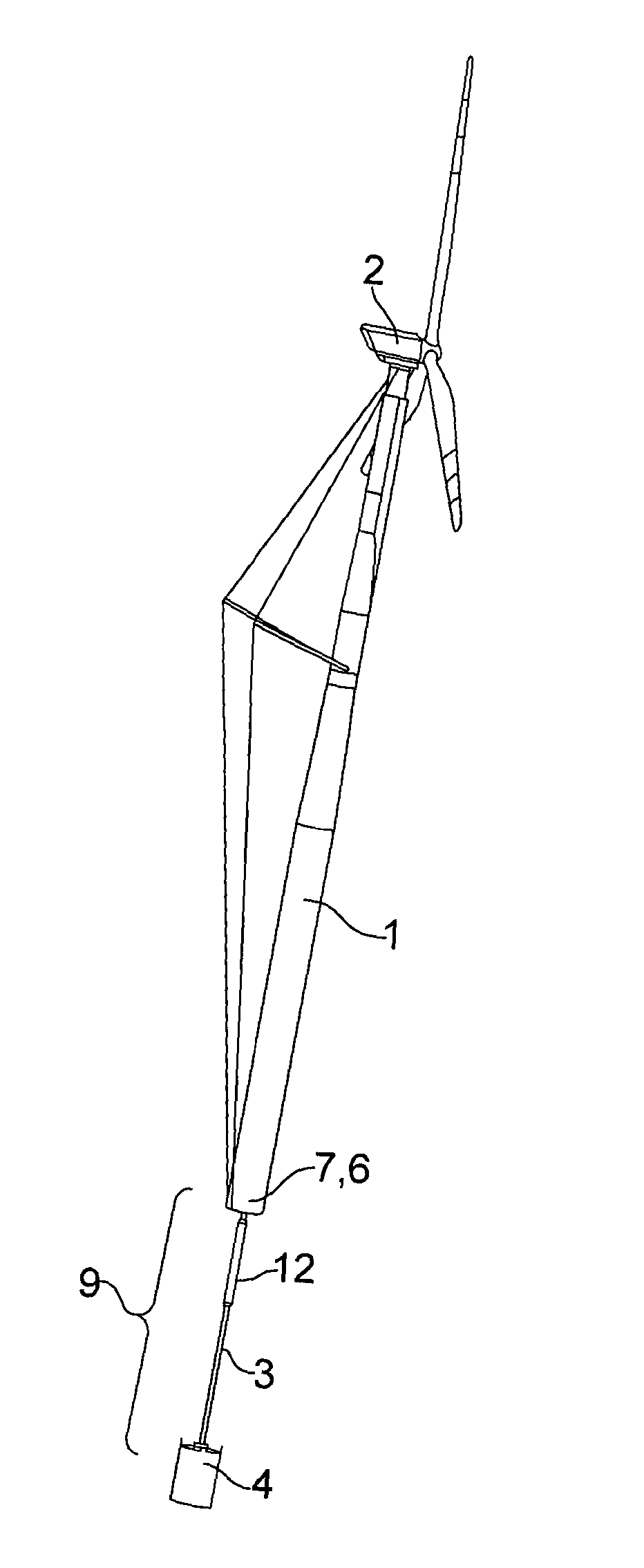
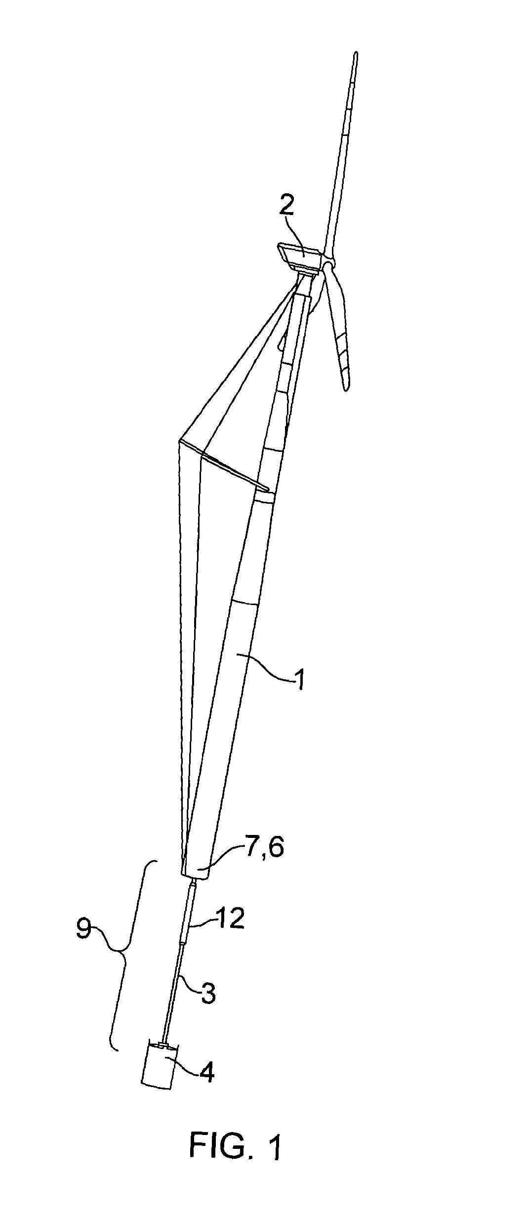
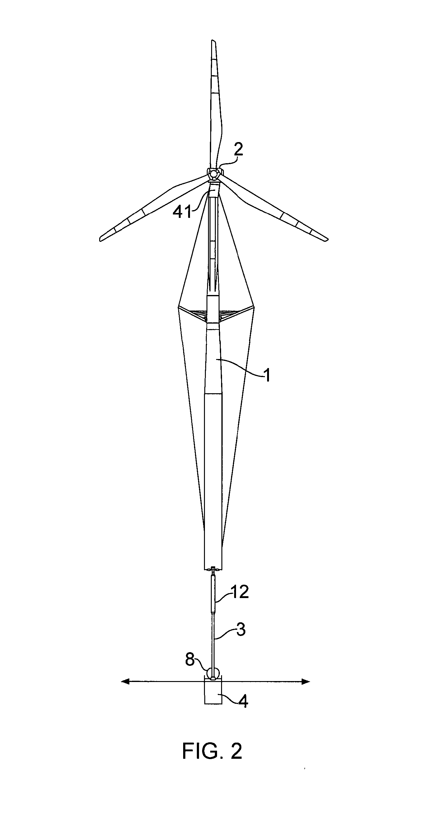
[0042]According to a preferred embodiment, the present invention is an offshore floating wind turbine generator comprising a 186-metre floating tower 1, of which 90 meters raises above sea level and 96 meters plunge into the ocean. A wind turbine 2 is mounted atop the floating tower. The floating tower 1 is anchored to the seabed by a tension leg 3 and an anchor, preferably a suction anchor 4 as shown in FIGS. 1 and 2. The tension leg is arranged to also resist torsion moments (torque) and has the form of a hollow pipe. An upper connection assembly 5 comprising an upper universal joint 6 and a yaw assembly 7 are arranged at the upper end of tension leg 3, while a lower universal joint 8 is arranged at the lower end of tension leg 3 at a connection point with the anchor 4. FIG. 1 further illustrates the wind direction, and an arrangement with spreader beams and tension cables for provid...


PUM

PropertyMeasurementUnit
diameteraaaaaaaaaa
angleaaaaaaaaaa
angleaaaaaaaaaa

Abstract

An offshore wind turbine generator comprises an elongated, buoyant tower, having an internal service tube, the service tube extending from the lower end of the tower to above the waterline when in use, a connection arrangement comprising an upper connection assembly, and a lower connection assembly. An intermediate tension / torsion leg is arranged between the upper and lower connection assemblies. The connection assembly is adapted for lowering and raising within the service tube.

Description

BACKGROUND[0001]1. Field of the Invention[0002]The present invention relates to wind turbine generators, more specifically to floating, offshore wind turbine generators.[0003]2. Brief Description of the Prior Art[0004]The development of wind turbine generators for generating power, preferably in the form of electric power, has moved steadily in the direction of larger wind turbines. Wind turbine generators with an output of about 5 MW and a rotor diameter of more than 115-125 m have now been designed and constructed. Wind turbine generators as large as 5 MW and more have been designed primarily with a view to being installed offshore due to a variety of technical, logistical and aesthetic considerations.[0005]Offshore wind turbine generators are in general either of the fixed installation type, or the floating type. The floating type of wind turbine generator presents a significant number of technical challenges in terms of installation, operation and maintenance. Such wind turbine ...

Claims


Application Information

Patent Timeline
Patent Type & Authority Applications(United States)
IPC IPC(8): F03D11/04
CPCF03D11/04F05B2240/95Y02E10/727F03D13/22F03D13/25B63B35/4406F03D13/10Y10T29/49631Y02E10/72B63B2035/446B63B21/502B63B21/27F05B2240/93F03D1/00
Inventor BORGEN, EYSTEIN
Owner SWAY AS
Why Eureka
Try Eureka