Method for operating a static gas turbine, and intake duct for intake air of a gas turbine

a gas turbine and static technology, applied in the direction of air intakes for fuel, machines/engines, combustion air/fuel air treatment, etc., can solve the problems of pressure reducing the power produced by the gas turbine and lowering the efficiency of the latter, so as to reduce the power produced by the gas turbine and eliminate the effect of pressure loss

Active Publication Date: 2014-07-17
SIEMENS ENERGY GLOBAL GMBH & CO KG
View PDF6 Cites 14 Cited by
  • Summary
  • Abstract
  • Description
  • Claims
  • Application Information

AI Technical Summary

Benefits of technology

[0008]The invention is based on the knowledge that, when the gas turbine is in operation, a loss of pressure results from the filtering of the air in the intake duct. This loss of pressure reduces the power produced by the gas turbine and lowers the efficiency of the latter. It is now provided, according to the invention, to eliminate this loss of pressure at short notice and for a short time, and thus to make an increase in the power of the gas turbine available to the generator connected thereto. In order to achieve this, a bypass for circumventing the filter or filters and / or at least one closable opening, arranged downstream of the filter or filters, is provided, preferably in the form of flaps, in a wall of the intake duct for letting in ambient air. With the aid of the bypass or, respectively, the closable openings, it is possible for ambient air which is at least partially unfiltered, but preferably entirely unfiltered, to flow into the compressor belonging to the gas turbine. By opening the flaps or, respectively, the bypass, it is possible to eliminate the power-reducing loss of pressure at the filters. The power output of the gas turbine is then increased by adding extra fuel, without this resulting in overfiring. Overfiring, which shortens the life of the components for guiding hot gases, can thus be avoided while still increasing power output.
[0009]This method is preferably used in the event of frequency support. However, as the particles suspended in the ambient air then flow into the gas turbine, it is advantageous to limit the time for this phase of operation of the gas turbine. It is preferably provided, in this context, that operation according to the invention is carried out for a maximum predefined time, for example 15 minutes. Following this phase of operation, i.e. immediately after or shortly after—within one hour, a compressor wash is preferably carried out. For this, it is known that a relatively large quantity of a cleaning fluid in drop form is introduced into the intake duct upstream of the compressor; this fluid can then flow into the compressor, where it can clean the blading of the compressor of the particles deposited thereon during operation with unfiltered air. It is thus possible for the ageing phenomena which briefly appear in the compressor to be reversed.

Problems solved by technology

This loss of pressure reduces the power produced by the gas turbine and lowers the efficiency of the latter.

Method used


Image

  • Method for operating a static gas turbine, and intake duct for intake air of a gas turbine
  • Method for operating a static gas turbine, and intake duct for intake air of a gas turbine
  • Method for operating a static gas turbine, and intake duct for intake air of a gas turbine

Examples


Embodiment Construction

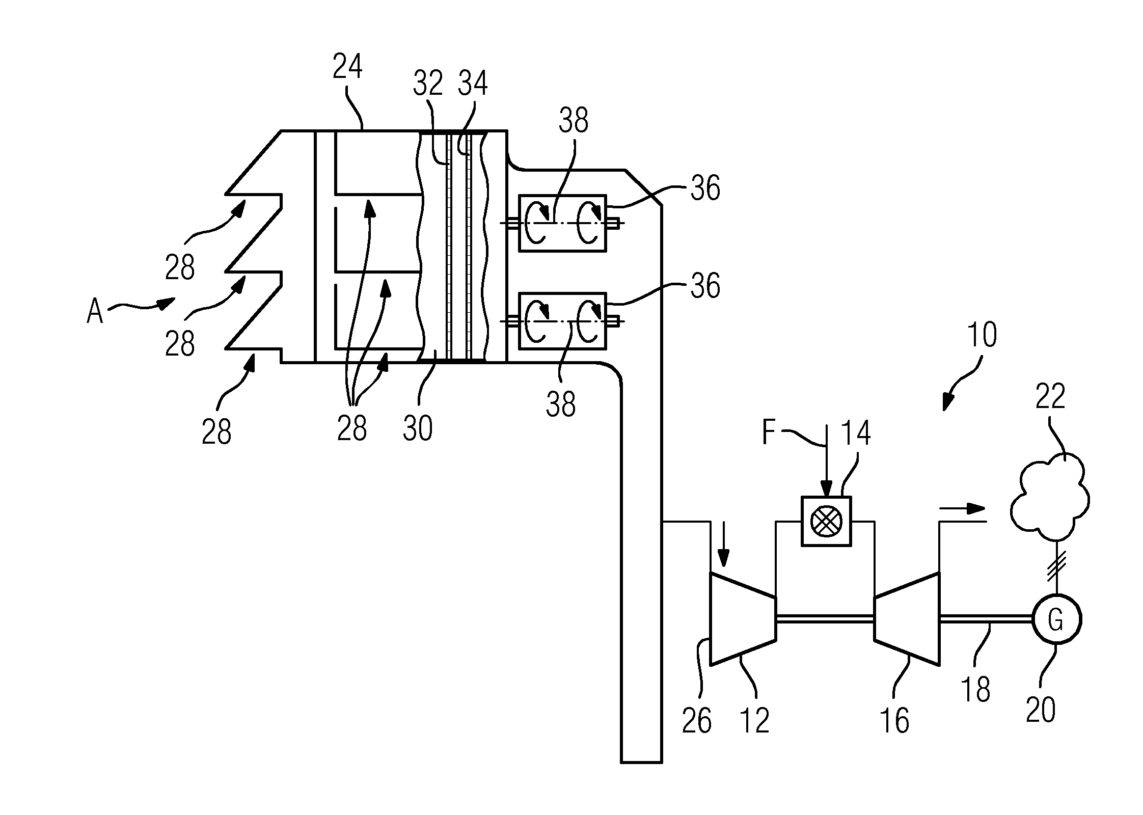
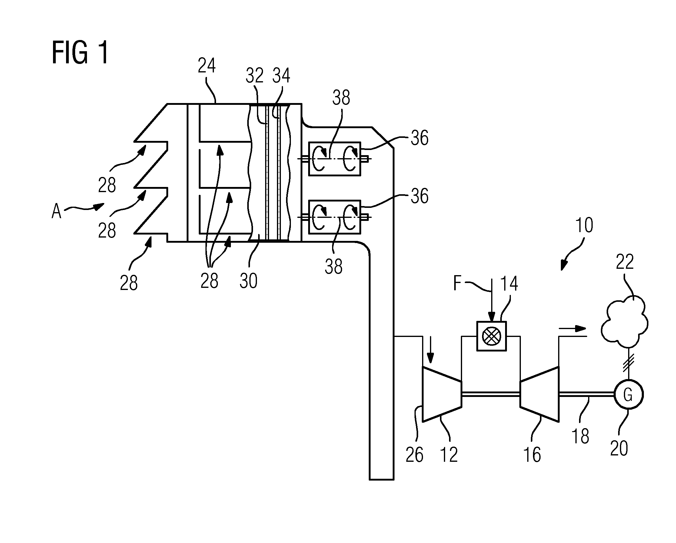
[0013]FIG. 1 schematically shows a static gas turbine 10 having a compressor 12, a combustor 14 and a turbine unit 16. A rotor 18 of the gas turbine 10 is connected to a generator 20, which feeds the electrical energy that it produces into an electrical distribution grid 22.

[0014]An intake duct 30 is provided in an intake housing 24 connected upstream of the compressor 12 and connects openings 28 of the intake housing 24 to the inlet 26 of the compressor 12. According to the exemplary embodiment shown, two filters 32, 34 are provided, connected one behind the other, in the intake duct 30. More or fewer filters may also be provided. The filters 32, 34 serve to clean the ambient air A drawn in of suspended particles and particles contained therein.

[0015]A plurality of large flaps 36, by means of which the intake duct 30 can be directly connected to the surroundings and isolated therefrom, are provided as closable openings downstream of the filters 32, 34 in a duct wall of the intake d...


PUM


Abstract

An ambient air intake duct of a static gas turbine is provided, having at least one filter, which is arranged in the intake duct, for cleaning the ambient air (A) that can flow through the intake duct. A method for operating a static gas turbine which is equipped with a filter for cleaning the ambient air (A) is also provided. To rapidly provide a higher level of gas turbine power to a generator, it is provided that, by means of a bypass or by means of flaps arranged downstream of the filter, partially to completely unfiltered ambient air (A) can temporarily flow into the compressor inlet.

Description

CROSS REFERENCE TO RELATED APPLICATIONS[0001]This application is the US National Stage of International Application No. PCT / EP2012 / 063777 filed Jul. 13, 2012, and claims the benefit thereof. The International Application claims the benefit of European Application No. EP11174857 filed Jul. 21, 2011. All of the applications are incorporated by reference herein in their entirety.FIELD OF INVENTION[0002]The invention relates to a method for operating a static gas turbine equipped with a filter for purifying the intake air. The invention also relates to an intake duct for intake air of a static gas turbine, having at least one filter arranged in the intake duct for purifying the intake air which can be made to flow through the intake duct.BACKGROUND OF INVENTION[0003]Static gas turbines are usually equipped with filters, arranged in the intake duct or in an intake housing, for the purpose of purifying the ambient air drawn in by the compressor. In this context, a plurality of filters are...

Claims


Application Information

Patent Timeline
Patent Type & Authority Applications(United States)
IPC IPC(8): F02M35/10
CPCF02M35/10F02C7/05F02C7/052
Inventor SCHNEIDER, OLIVER
Owner SIEMENS ENERGY GLOBAL GMBH & CO KG
Why Eureka
Try Eureka