High efficiency, high pressure gas turbine engine fuel supply system and method

a gas turbine engine, high-efficiency technology, applied in the direction of engine components, hot gas positive displacement engine plants, feed systems, etc., can solve the problems of unsatisfactory high fuel temperature, and achieve the effect of reducing power extraction, minimizing power extraction and heat generation

Active Publication Date: 2014-07-17
HONEYWELL INT INC
View PDF1 Cites 14 Cited by
  • Summary
  • Abstract
  • Description
  • Claims
  • Application Information

AI Technical Summary

Benefits of technology

[0031]In the first control position, which is the position depicted in FIG. 2, the pump control valve element 226 fluidly isolates the supercharger pump inlet port 234, and thus the supercharger pump inlet 126, from the boost pump outlet 114, and fluidly couples the supercharger pump outlet port 236, and thus the supercharger pump outlet 128, to the supercharger pump vent port 238. The pump control valve element 226 also couples the secondary gear pump outlet port 246 to the pressurizing valve control port 244, and fluidly isolates the secondary gear pump outlet port 246 from the primary gear pump outlet port 248. Thus, as previously noted, only the primary gear pump 104 supplies pressurized fuel to the downstream fuel loads. At the same time, the secondary gear pump 106 is routed to the pressurizing valve 128, which idles the pressure rise of the secondary gear pump 106 to a relatively low differential pressure, thereby minimizing power extraction and heat generation. It is additionally noted that the supercharger pump 108 is preferably disengaged from a fluid source, further reducing power extraction.
[0032]When the pump control pilot valve element 204 is in the second pilot position, the low-pressure supply port 212 is fluidly coupled to the control pressure outlet port 222, the supercharger feed inlet port 214 is fluidly coupled to the supercharger feed outlet port 216, and the control pressure inlet port 218 is fluidly isolated from the control pressure outlet port 222. Because the control signal port 228 is in fluid communication with the control pressure outlet port 222, the control signal supplied to the control signal port 228 is a relatively low fluid pressure signal from the boost pump outlet 126. The combined fluid pressure forces acting on the pump control valve element 226 overcome the relatively low fluid pressure signal and the spring force supplied from the bias spring 245 to move (or maintain) the pump control valve element 226 to (or in) the second control position.

Problems solved by technology

The known fuel supply systems described above generally operate safely and robustly, but can exhibit certain drawbacks.
For example, recirculating the excess fuel from the main fuel pump wastes energy by generating heat, and can lead to undesirably high fuel temperatures.

Method used


Image

  • High efficiency, high pressure gas turbine engine fuel supply system and method
  • High efficiency, high pressure gas turbine engine fuel supply system and method
  • High efficiency, high pressure gas turbine engine fuel supply system and method

Examples


Embodiment Construction

[0015]The following detailed description is merely exemplary in nature and is not intended to limit the invention or the application and uses of the invention. As used herein, the word “exemplary” means “serving as an example, instance, or illustration.” Thus, any embodiment described herein as “exemplary” is not necessarily to be construed as preferred or advantageous over other embodiments. All of the embodiments described herein are exemplary embodiments provided to enable persons skilled in the art to make or use the invention and not to limit the scope of the invention which is defined by the claims. Furthermore, there is no intention to be bound by any expressed or implied theory presented in the preceding technical field, background, brief summary, or the following detailed description.

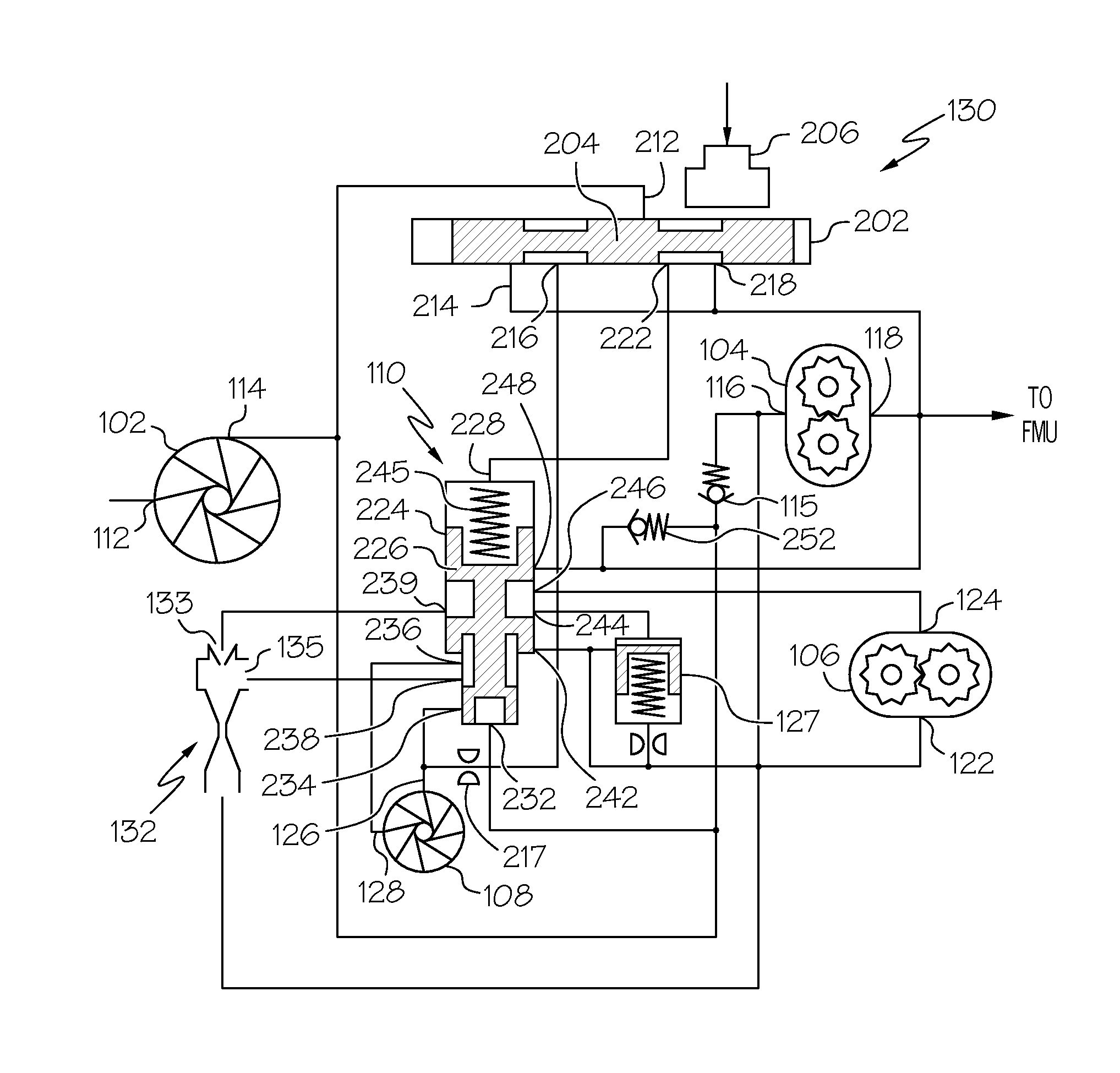
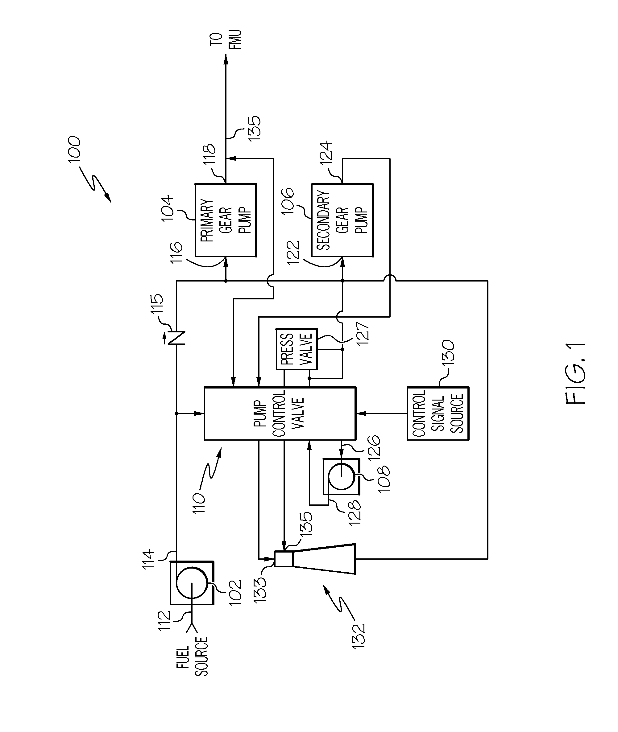
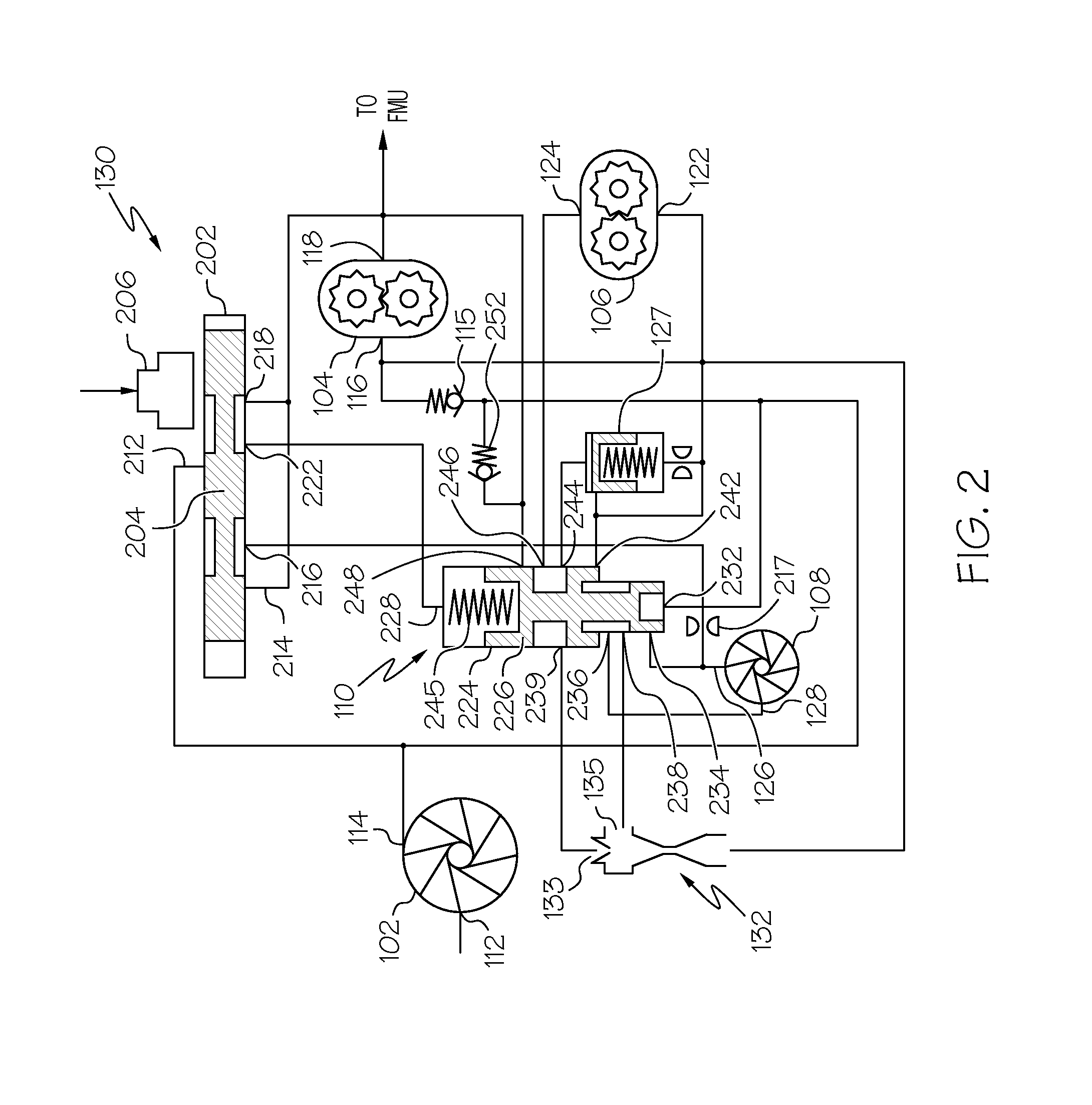
[0016]Referring first to FIG. 1, a functional block diagram of an embodiment of the fuel supply system 100 is depicted, and includes a boost pump 102, a primary gear pump 104, a secondary gear ...


PUM


Abstract

A gas turbine engine fuel supply system includes a primary gear pump and a secondary gear pump. The primary gear pump always actively delivers fuel to the downstream fuel system, and is sized to supply 100% of the burn flow needed at a select low demand condition. The secondary gear pump is sized to make up the remainder of the flow at high demand conditions, and actively delivers fuel to the downstream fuel system only during those conditions. To supply discharge fuel pressures in excess of gear pump capability, a supercharger pump is disposed upstream of the primary and secondary gear pumps. The supercharger pump is preferably activated only during high demand conditions as an additional energy conservation measure.

Description

CROSS-REFERENCE TO RELATED APPLICATIONS[0001]This application claims the benefit of the benefit of U.S. Provisional Application No. 61 / 753,595, filed Jan. 17, 2013.TECHNICAL FIELD[0002]The present invention generally relates to gas turbine engine fuel control, and more particularly relates to a system and method for selectively supplying fuel at multiple pressures to a gas turbine engine.BACKGROUND[0003]Typical gas turbine engine fuel supply systems include a fuel source, such as a fuel tank, and a main fuel pump that receives fuel drawn from the fuel source and delivers pressurized fuel to the fuel manifolds in the engine combustor via a main supply line. The main fuel pump is typically implemented using a positive displacement pump that is driven directly by the engine gearbox. Thus, the fuel flow supplied by the main fuel pump is proportional to engine speed.[0004]The fixed displacement of a main fuel pump is typically sized to produce the fuel flow that is needed to run the engi...

Claims


Application Information

Patent Timeline
Patent Type & Authority Applications(United States)
IPC IPC(8): F02C7/236
CPCF02C7/236
Inventor ZIELINSKI, EDWARDFUTA, PAUL W.TUTTLE, DAVID
Owner HONEYWELL INT INC
Why Eureka
Try Eureka