Algae reduction device for air handler systems

a technology of air handler and reduction device, which is applied in the direction of space heating and ventilation, lighting and heating apparatus, heating types, etc., can solve the problems of algae growth, possible corrosion, condensation, etc., and achieve the effect of reducing the need for a powerful and expensive pump, reducing the strain on the pump, and increasing the fluid latency of the pan

Inactive Publication Date: 2019-06-20
VANDERHAAR WILL
View PDF13 Cites 0 Cited by
  • Summary
  • Abstract
  • Description
  • Claims
  • Application Information

AI Technical Summary

Benefits of technology

[0018]In another embodiment, the pump is controlled to pulse the fluid during operation. The fluid drains from the pan via the drain. Pulsed delivery of the fluid increases latency of the fluid in the pan and drain to enable the fluid to inhibit algae growth during a longer period of time for the same, or less, volume of fluid.
[0019]The present invention is specifically designed for reliability and longevity. Preferably the reservoir is positioned in a manner that utilizes the force of gravity to draw fluid from the reservoir into the drain pan and reduces strain on the pump. In the embodiment where the fluid pump pulses the fluid into the drain pan, the pump has time to cool and thus maintains a desirable temperature. Utilizing fluid pulses in combination with a gravity assist orientation of the operative components reduces the need for a powerful and expensive pump. Additionally, heat generated by the pump motor is minimized due to the pulsed delivery of fluid. Pulsed delivery of fluid increases the time latency of the fluid within the pan in a tightly regulated fashion with a minimum of fluid volume being wasted. The pulsed delivery may be periodic, e.g. daily or weekly.
[0020]The combination of a gravity fed apparatus and the pulsing of the pump motor greatly increases the pump life and greatly minimizes the volume of fluid delivered from the reservoir to the drain pan. This is important because the reservoir contains only a finite amount of fluid and systems that waste fluid require more frequent refilling of the reservoir. Furthermore the pulsing of the pump motor in combination with the force of gravity can enable use of increase pressure in the tube to assure that the tube remains unobstructed. The pressure need not be maintained by the pump and the pulsing of the pump reduces wear on the pump motor and energy consumed by the pump motor. Reducing energy consumed by the pump motor is particularly useful in embodiments where the system is battery-powered.
[0021]The air handler can be used to deliver heat. Mounting the reservoir outside of the air handler housing reduces heat stress to the pump, and to the reservoir and its contents. Thus the reservoir can be made from heat resistant plastic, and the volume of fluid within the reservoir can reduce heat transfer from the housing to the pump when the pump operates. Heat reduction improves pump life and reduces wear.
[0022]The combination of pulsed delivery of fluid, gravity feeding the pan from the reservoir, and pulsed operation of the pump reduces heat related stress on the pump and thus improves pump longevity. Further the use of the fluid reservoir as a heat sink, or insulator, for the pump further improves pump longevity.

Problems solved by technology

Corrosion is likely anywhere air changes temperature and condensation occurs.
One problem shared by manufacturers of air handlers as well as residential and commercial users of air handling systems is that condensation can lead to growth of algae and other undesirable biological life.
Algae can grow rapidly under ideal conditions and is known to clog pan drains in air handlers.
This drain can become plugged with algae when algae grow in the pan causing pan to overflow.
Pan overflow may corrode, or otherwise damage the air handler.
Nearby flooring, walls, and other surrounding structures and equipment may also be damaged.
Over time the damage can be considerable.
Puddles may be undesirably aromatic.

Method used


Image

  • Algae reduction device for air handler systems
  • Algae reduction device for air handler systems
  • Algae reduction device for air handler systems

Examples


Embodiment Construction

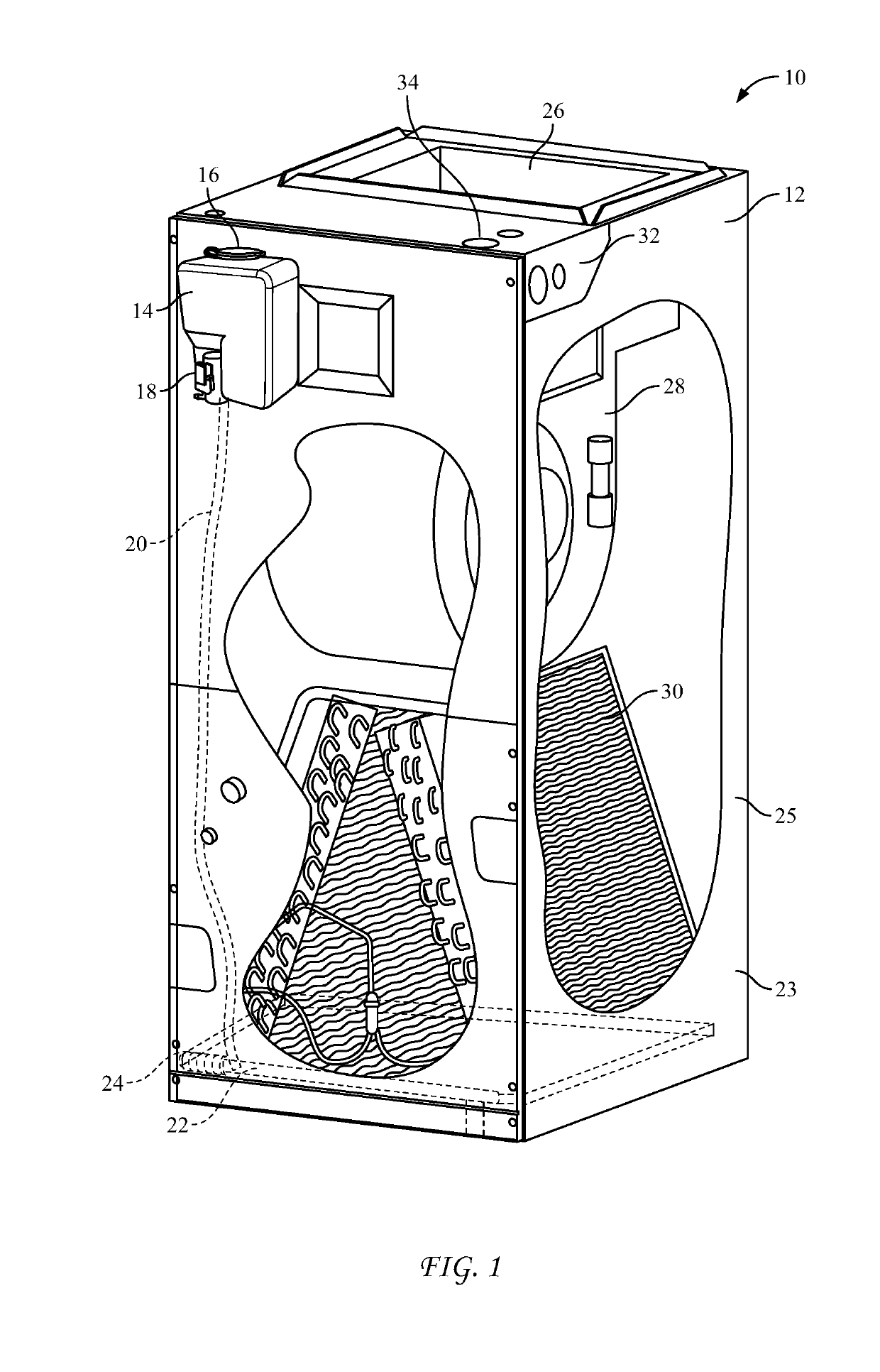
[0031]FIG. 1 shows an air handling system generally designated with the reference numeral 10. The air handling system 10 is an air handler with the housing 12. The housing 12 includes a kit of parts attached to the housing 12 for reducing algae growth.

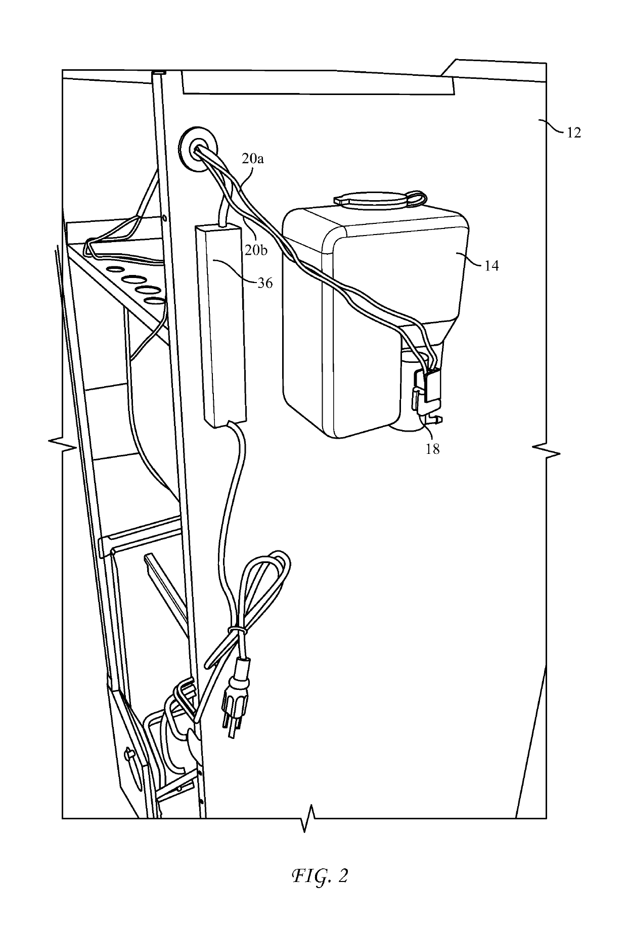
[0032]The kit of parts includes the reservoir 14 having a removable lid 16 and a pump motor 18. The reservoir 14 is preferably a heat resistant plastic reservoir designed to hold fluids having a pH range of 2-7.

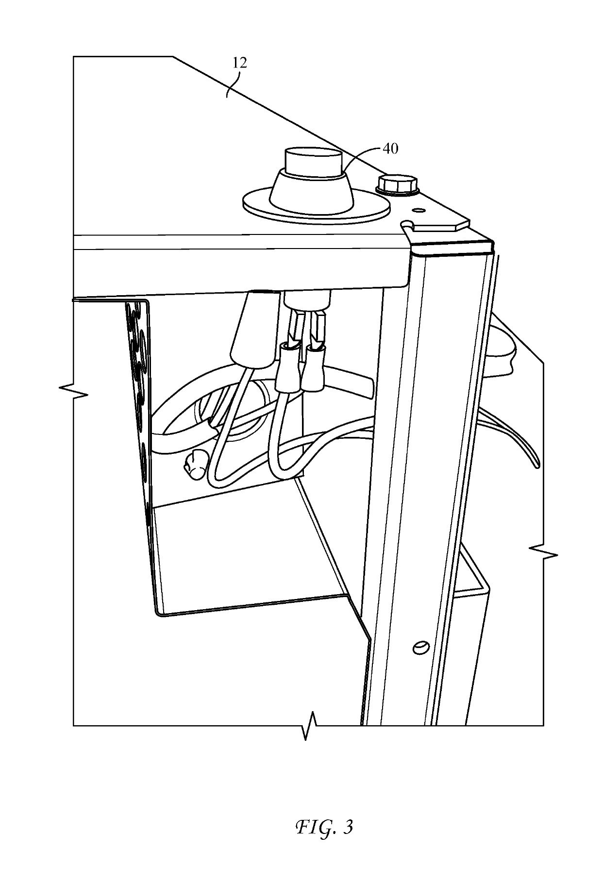
[0033]The tube 20 attaches to the pump motor for delivering fluid from the reservoir 14. The housing 12 includes a pan 22 removeably mounted at the bottom 23 of the housing 12 for capturing fluid such as condensate and leaking fluid. The tube 20 attaches to the pan 22 with a tube clasp 24.

[0034]Preferably the tube 20 is manufactured from a flexible and heat resistant material such as silicon. The housing includes a blower 28 and at least one heat exchanger 30. The blower 28 draws air past the heat exchanger 30 to either heat or ...


PUM


Abstract

A system, and kit of parts capable of retrofit and use with an air handling system. The system includes housing and a drain pan with a raised edge. The kit includes a fluid reservoir attachable to the housing for holding fluid, a pump mounted on the fluid reservoir, and a tube to transfer the fluid from the fluid reservoir to the drain pan. The drain pan includes a drain. A tube clasp made from a single piece of material folded upon itself to define an opening for receiving the tube. The tube clasp has a spring loaded hinge. The open portion includes a flared section to enable the open portion to removeably clasp the raised edge of the drain pan. In one embodiment the pump intermittently pumps fluid into the pan to increase latency of the fluid in the pan and drain to enable the fluid to inhibit algae growth.

Description

FIELD OF THE INVENTION[0001]This invention relates generally to air handling systems, and particularly to improvements to air handling systems capable of reducing algae growth.BACKGROUND OF THE INVENTION[0002]Air handling systems are often termed air handlers or air handling units. Such air handling systems to regulate and circulate air as part of a heating, ventilating and air-conditioning (HVAC) system. Air handlers usually include metal housing containing a blower, heating or cooling elements. Residential air handlers typically include both heating and cooling elements. Commercial air handlers may be specifically designed to circulate heat in a large structure or vehicle. In some cases air handlers are mounted on a rooftop. In other cases air handlers are mounted in a basement in conjunction with the boiler or other heating device.[0003]Air handlers usually connect to a duct work ventilation system that circulates and distributes air from the air handler to within a structure.[00...

Claims


Application Information

Patent Timeline
Patent Type & Authority Applications(United States)
IPC IPC(8): F24F13/22F24D19/08F24D19/10
CPCF24F13/22F24D19/088F24D19/10F24F2013/221
Inventor VANDERHAAR, WILL
Owner VANDERHAAR WILL
Why Eureka
Try Eureka