Eureka AIR delivers breakthrough ideas for toughest innovation challenges, trusted by R&D personnel around the world.

Power Supply Device for Surgical Instrument, Using Ultrasonic Waves

a power supply device and surgical instrument technology, applied in the field of ultrasonic wave devices for supplying power to surgical instruments, can solve the problems of unfavorable user intentions for cutting and/or surgical apparatuses are liable to easy failure, and the speed and degree of cutting and stopping bleeding at surgical sites cannot be freely controlled by the user's intention, so as to prevent unreasonably high vibration, minimize heat generation of surgical instruments, and control the speed and degree of cutting and

Inactive Publication Date: 2016-07-28
KIM EUNGKOOK
View PDF3 Cites 0 Cited by
  • Summary
  • Abstract
  • Description
  • Claims
  • Application Information

AI Technical Summary

Benefits of technology

The power supply device for a surgical apparatus using ultrasonic waves allows for easy control of cutting and bleeding speed by the user through intensity control of the current flow. It also minimizes heat generation by preventing unreasonable vibration and ultrasonic wave generation. The device includes a current regulating unit that can be controlled by an independent controller, improving user convenience.

Problems solved by technology

However, those apparatuses equipped with power supply devices which applies power at a constant intensity of current are commercialized, and there is yet no power supply device which can supply power suitable for a surgical apparatus using ultrasonic waves which have been developed.
Accordingly, since the surgical apparatuses using ultrasonic waves use power supply devices which can supply a constant current only, such surgical apparatuses are liable to easy failure due to excessive heat generation.
Such problem also involves the problem that the cutting and / or stopping bleeding at a surgical site cannot be freely controlled by the intention of the user.
However, such configuration also cannot dissolve the problem that cannot minimize heat generation.
In addition, since a user must control the current using the control switch continuously, leading to fatigue in the hand, deteriorating user convenience, the technical problem still exists to be dissolved.

Method used


Image

  • Power Supply Device for Surgical Instrument, Using Ultrasonic Waves
  • Power Supply Device for Surgical Instrument, Using Ultrasonic Waves
  • Power Supply Device for Surgical Instrument, Using Ultrasonic Waves

Examples


Embodiment Construction

Technical Objects

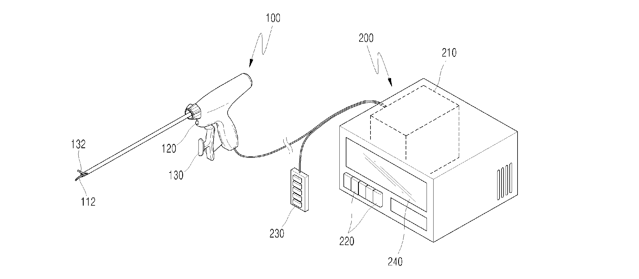
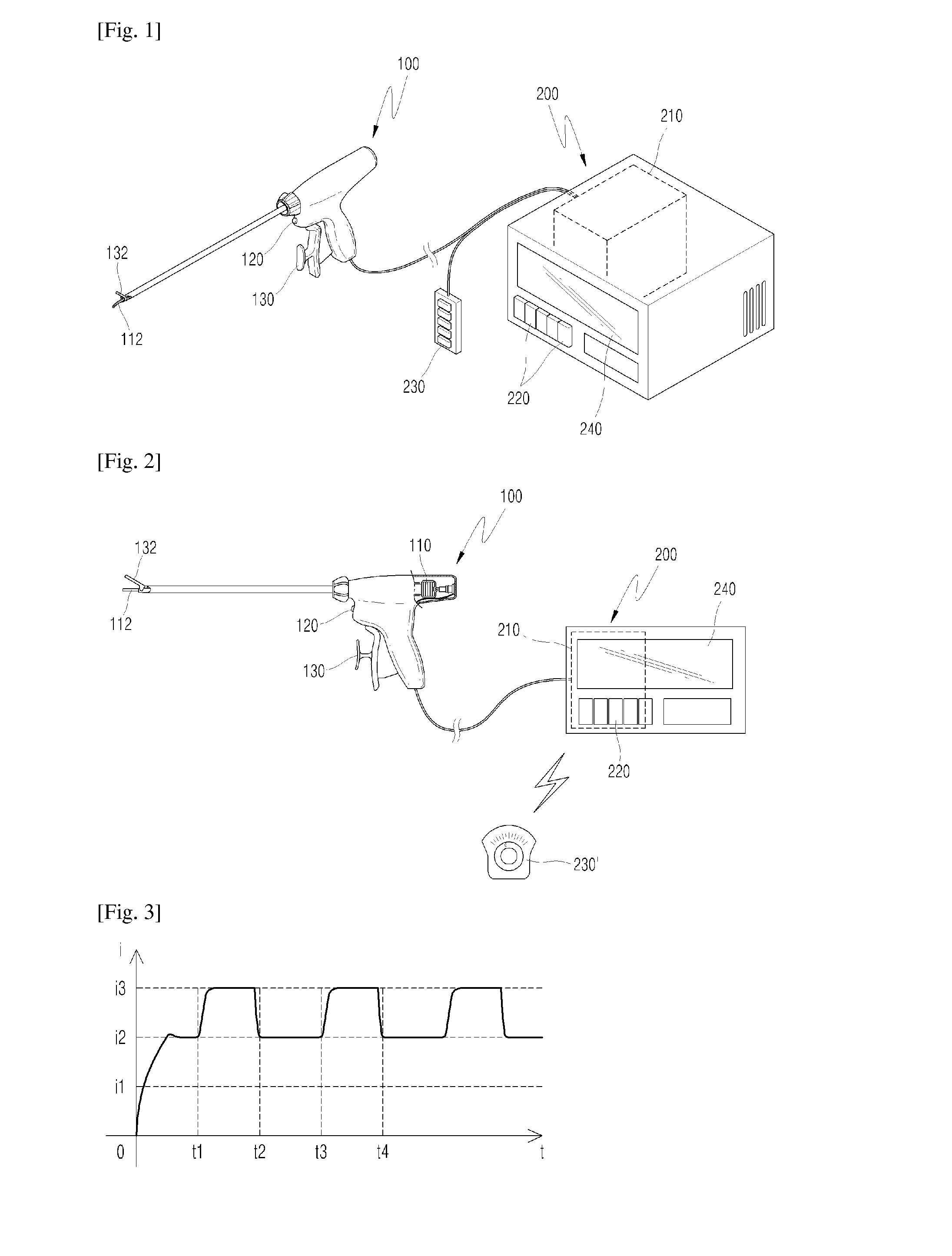
[0008]To solve above described problem, an aspect of the present invention is to provide a power supply device for a surgical apparatus using ultrasonic waves which can control the speed of degree of cutting and stopping bleeding at a surgical site according to the intention of a user, while enables to minimize heat generation of the surgical apparatus using ultrasonic waves.

[0009]In addition, another aspect of the present invention is to provide a power supply device for a surgical apparatus using ultrasonic wave which can improve user convenience.

[0010]The invention is not restricted to the embodiments set forth herein. The above and other aspects of the invention will become apparent to those skilled in the art to which the invention pertains by referencing the detailed description of the invention below.

Means for Achieving the Technical Object

[0011]The technical object of the present invention to solve above described problem is to provide a power supply device ...


PUM


Abstract

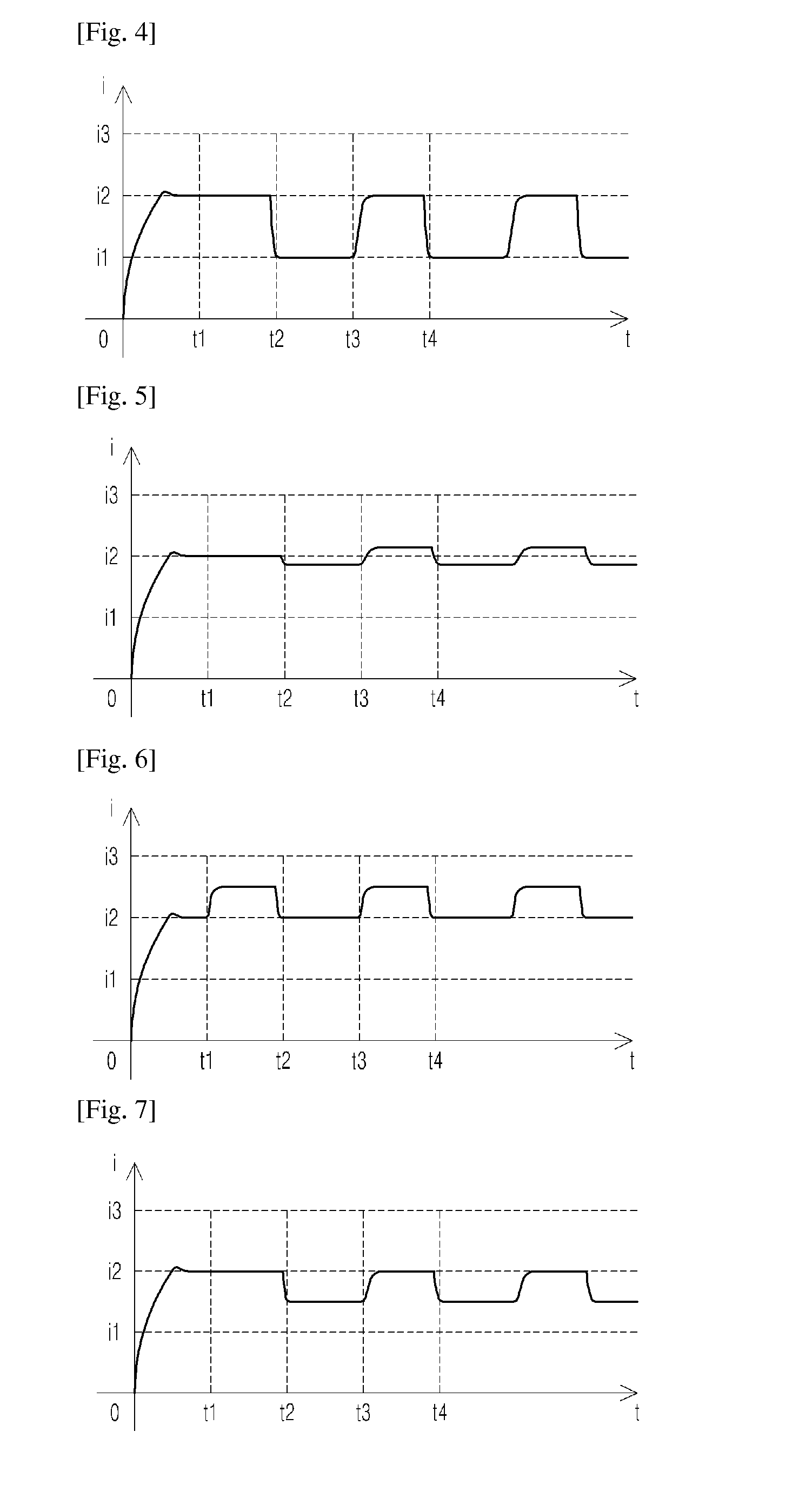
The present invention relates to a device for supplying power to a surgical instrument for amputating a surgical site or stopping bleeding by using ultrasonic waves, comprising a control unit for controlling the intensity of current flowing into a vibrator, which is provided at the surgical instrument to control the intensity of ultrasonic waves oscillated at the surgical instrument, wherein the current control unit controls the intensity of current flowing into the vibrator such that weakening the intensity of current, flowing into the vibrator, for a predetermined time period can be periodically repeated.

Description

TECHNICAL FIELD[0001]The present invention relates to a device for supplying power to a surgical apparatus using ultrasonic waves, more particularly, to a device for supplying power to a surgical operation apparatus using heat generation of ultrasonic wave. The degree of amputating a surgical site or stopping bleeding can be freely and easily adjusted according to the intension of a user, while minimizing the heat generation of the surgical apparatus using ultrasonic waves, so that the user can operate the apparatus with improved convenience.BACKGROUND ART[0002]Recently, surgical apparatuses using ultrasonic waves are being developed. Among them, the surgical apparatus such as Harmonic Scalpel which can cut and stop bleeding at the same time is playing an important role in laparoscopic surgery.[0003]However, those apparatuses equipped with power supply devices which applies power at a constant intensity of current are commercialized, and there is yet no power supply device which can...

Claims


Application Information

Patent Timeline
Patent Type & Authority Applications(United States)
IPC IPC(8): A61B17/32
CPCA61B17/320068A61B2017/320072A61B2560/0214A61B17/320092A61B2018/0072
Inventor KIM, EUNGKOOK
Owner KIM EUNGKOOK
Why Eureka
Eureka Blog
Learn More