
One-step starting carburetor

a carburetor and one-step technology, applied in the field of carburetor, can solve the problems of complicated operation and affect the normal work of the engine, and achieve the effects of improving the engine's performance, reducing fuel consumption, and increasing the life of the engin

Active Publication Date: 2014-07-17
CHEN QIAN
View PDF10 Cites 6 Cited by
  • Summary
  • Abstract
  • Description
  • Claims
  • Application Information

AI Technical Summary

Benefits of technology

The invention is a carburetor that improves engine performance and reduces fuel consumption. It uses a pulse generator and an oil pumping unit connected through a pipe line. The carburetor has two types of pulse: the crowding pulse and the normal pulse. The crowding pulse helps start the engine at low temperature by pushing the metering diaphragm and concentrating the fuel-air mixture in the carburetor. The normal pulse provides pumping force for the carburetor's normal working mode. The invention also includes an air vent for temperature control, which discharges the crowding pulse at high temperature and ensures a proper engine starting. Overall, the invention improves engine performance and increases lifespan while reducing fuel consumption.

Problems solved by technology

Thus these operations are complicated and affect the normal work of the engine.

Method used


Image

  • One-step starting carburetor
  • One-step starting carburetor
  • One-step starting carburetor

Examples


embodiment one

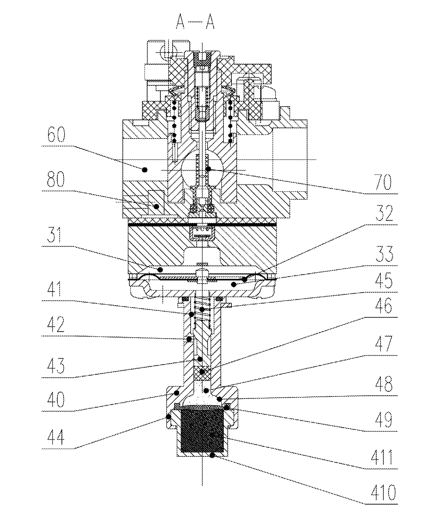
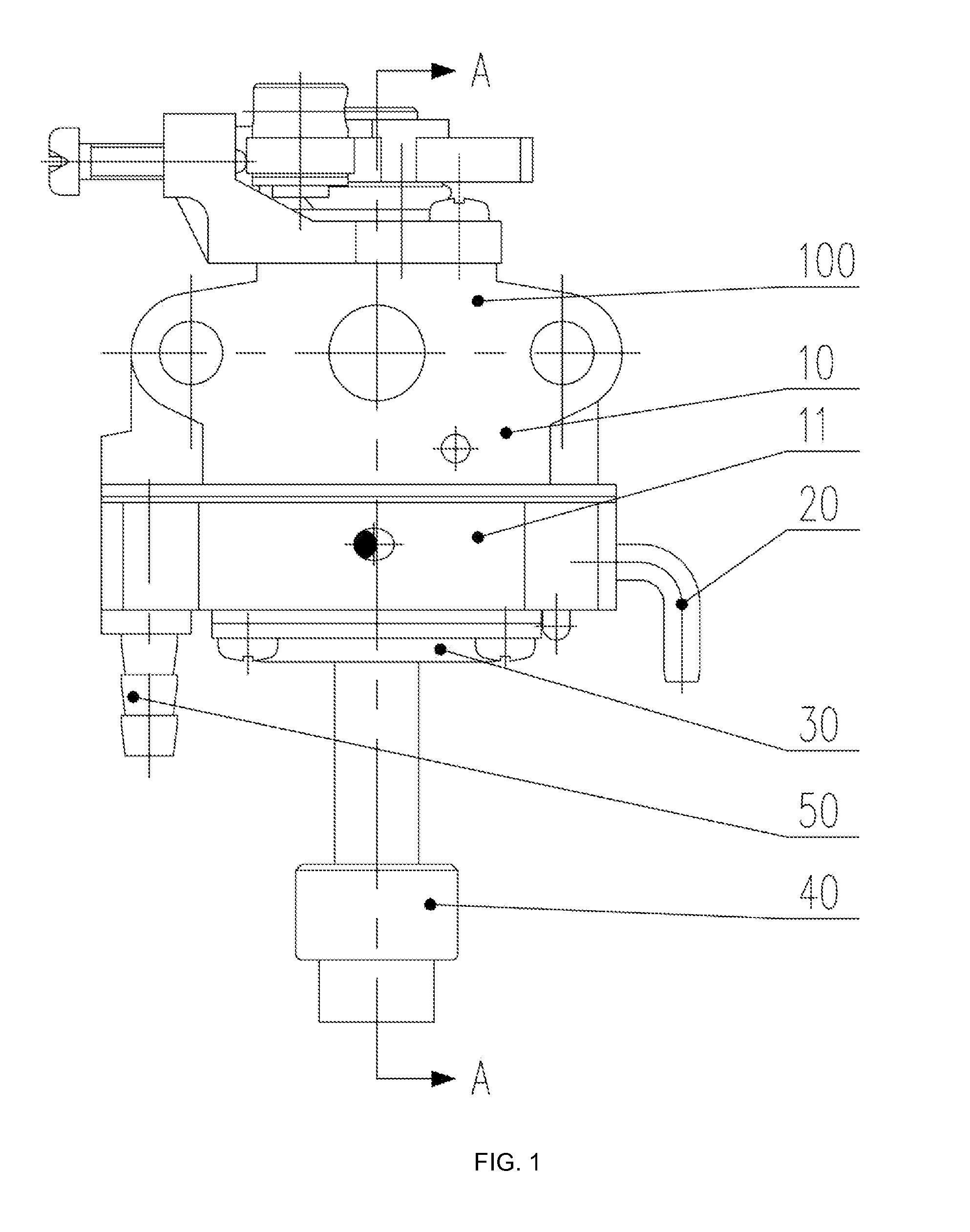
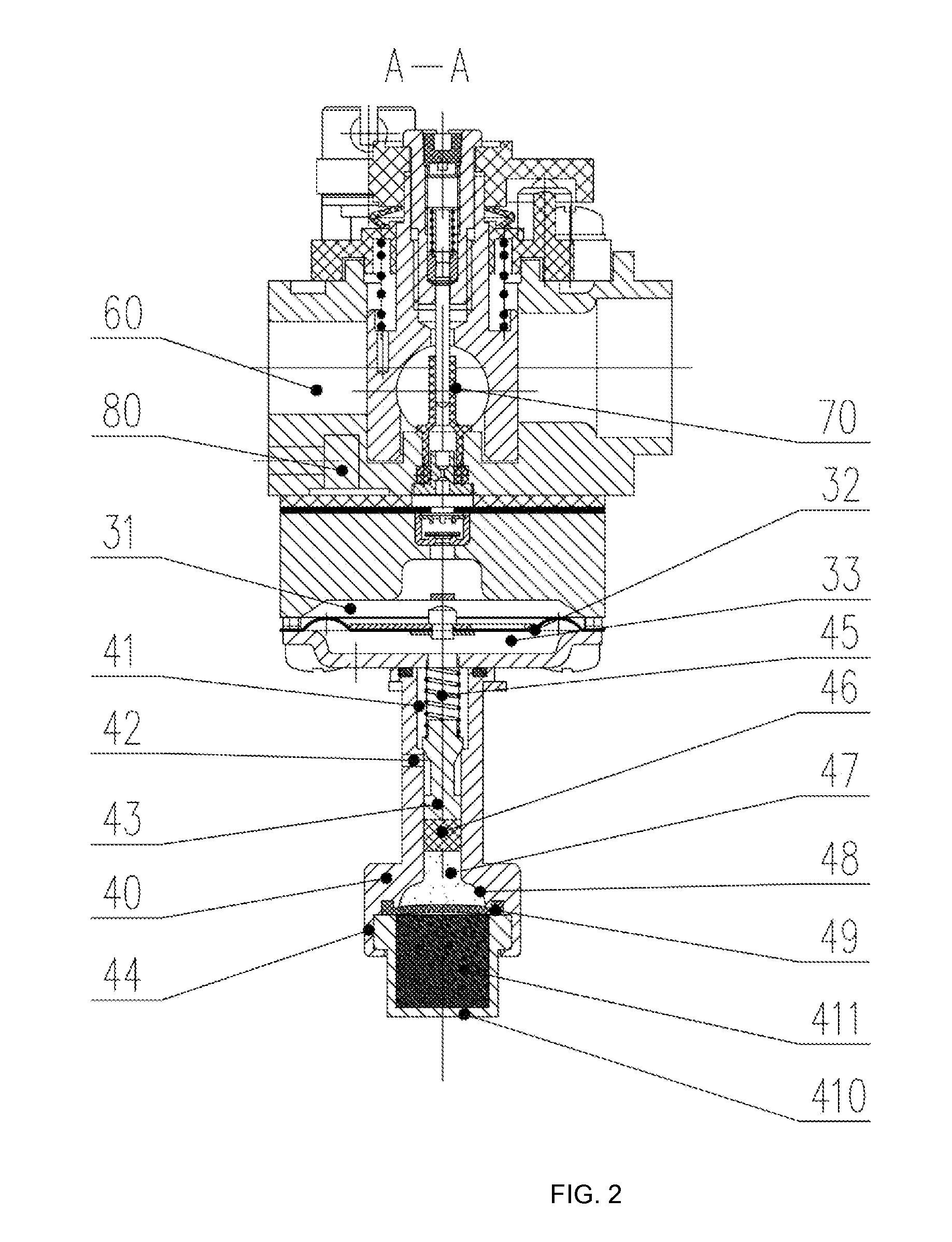
[0047]Now refers to the drawings, FIG. 1-2 describe an embodiment according to the overall structure of the one-step starting carburetor 100 of the present invention. As shown in the FIG. 1 that the carburetor 100 has a body 10, a middle body 11, a fuel inlet pipe 50, a fuel outlet pipe 20, a lower cover 30 and a temperature controller 40 which is connected with the lower cover 30. The body 10 includes a pulse chamber 80, a main nozzle 70 and a mixing chamber 60. The middle body 11 includes the lower cover 30, a metering chamber 31 and a metering diaphragm 32 which is in the metering chamber 31 and a chamber 33 of the lower cover. The temperature controller 40 includes a copper base 410, paraffin 411, a diaphragm 49, a fluid medium 47, a plunger 46, a top pole 43, an air vent 42 and a return spring 45.

[0048]Further according to FIG. 2, the temperature controller 40 herein is described in detail. The section of copper base 410, in which the paraffin 411 is placed, is in a rectangle s...

embodiment two

[0062]Now referring to the drawings 4 and 9, FIG. 9 is an exploded view of the diaphragm type oil pumping unit 300. The diaphragm type oil pumping unit 300 includes a support 310, a middle body 340 and a lower cover 350. The support 310 is connected with the middle body 340 and the lower cover 350 by bolts. A fuel inlet pipe 370, a solenoid valve 360 and a fuel outlet pipe 380 are set up on the support 310. A chamber 312, a plane A and a plane B are set up at the bottom of the support 310. A pulse chamber E and a small hole 346 are set up in the upper part of the middle body 340, and a pulse chamber F is set up at the bottom of the middle body 340. An oil pumping diaphragm 320 and a sealing gasket 330 are set up between the middle body 340 and the support 310. A tongue piece C and a tongue piece D are set up on the oil pumping diaphragm 320. A lower sealing gasket 342, a diaphragm part 343 and a lower sealing gasket 344 are set up between the middle body 340 and the lower cover 350....


PUM


Abstract

A one-step starting carburetor includes a body, and a pulse generator and an oil pumping unit which are connected with the body. The oil pumping unit can produce an oil pumping function to pump fuel from an oiler to the carburetor when a flywheel of an engine is revolving. When the carburetor is operating, it only needs to pull a starting line and does not need to extrude an oil pumping ball to pump the fuel for the carburetor or to close a choke valve. After hearing a voice like ‘poop-poop’, it does not need to half open the choke valve to warm the engine or to open the choke valve after warming the engine. Thus the operation of the carburetor is simple for users' convenience.

Description

TECHNICAL FIELD[0001]The embodiments described herein relate to a carburetor, more particularly to a one-step starting carburetor.BACKGROUND OF THE INVENTION[0002]The continuing improvements of society and economic have provided a good platform for further development of the gasoline engine industry. Hereinto the gasoline engine auxiliary industry has developed rapidly because of the development of the gasoline engine industry. As one of the gasoline engine auxiliary industries, the carburetor industry developed rapidly.[0003]Carburetor is an apparatus which mixes certain amount of fuel and air in order to make the petrol engine operate regularly. In the start-up process of an engine, the amount of air is reduced and the density of mixture gas into the engine is increased by closing the induction passage, so that the engine starts. However, the existing carburetor has certain drawbacks. Before those carburetors leave factories, based on its technique feature which has matched with e...

Claims


Application Information

Patent Timeline
Patent Type & Authority Applications(United States)
IPC IPC(8): F02M7/00
CPCF02M7/00F02M1/08F02M7/083F02M1/10F02M1/16F02M17/04
Inventor CHEN, QIANJIA, YONGCHENG
Owner CHEN QIAN
Learn More