Injection molding method and injection molding machine

a technology of injection molding machine and injection molding method, which is applied in the direction of manufacturing tools, drawing profiling tools, food shaping, etc., can solve the problems of affecting the appearance of molded objects, affecting the positioning accuracy of molded objects, and affecting the quality of molded objects, so as to improve the positioning accuracy of the film and the appearance of the molded object. , the effect of reducing the occurrence of failures

Active Publication Date: 2014-07-17
PANASONIC INTELLECTUAL PROPERTY MANAGEMENT CO LTD
View PDF1 Cites 6 Cited by
  • Summary
  • Abstract
  • Description
  • Claims
  • Application Information

AI Technical Summary

Benefits of technology

[0018]As has been discussed, the base film stretched according to the recessed shape of the first die may have foreign matters causing failures. Moreover, a break on the base film may cause variations in tension in the film when the film is wound up. This may lead to a displacement of winding or a pattern on the film and deteriorate the positioning accuracy of the film. Hence, a break on the base film may deteriorate the appearance of the molded article. In the case where the transfer film is partially stacked on the base film, that is, the transfer film is discontinuously stacked in the longitudinal direction of the base film, the transfer film on the base film needs to be located at a proper position between the first die and the second die at each time of injection molding. This requires the film to be positioned with high accuracy.
[0019]An object of the present invention is to provide an injection molding method and an injection molding machine that hardly break a base film when the base film is separated from the recessed portion of a first die after a mold is opened.
[0030]According to the present invention, after the dies are opened, the base film separated from the first die is hardly broken. Thus, fragments of the base film can be reduced so as to lower the occurrence of failures caused by foreign matters. Moreover, the present invention can improve the positioning accuracy of the film and the appearance of the molded article.

Problems solved by technology

In the typical injection molding process, however, if the molded article has a deeply drawn shape, the base film may be stretched beyond its elastic limit and locally have an extremely small thickness.
Hence, when the base film is removed from the recessed portion of the first die after the mold is opened, a rapid force applied to the film may cause an impact force exceeding the critical stress on an extremely thin portion of the base film.
Thus, the base film may be broken with fragments scattered in the mold.
Such fragments may become foreign matters causing failures in the subsequent injection molding.
When the base film is peeled from the recessed portion of the first die after the mold is opened, adhesion caused by static electricity between the first die and the base film may apply a stress exceeding the critical stress on a thin portion of the base film, leading to a break on the base film.
For example, failures are caused by foreign matters such as fragments of the base film in the molded article.
As has been discussed, the base film stretched according to the recessed shape of the first die may have foreign matters causing failures.
Moreover, a break on the base film may cause variations in tension in the film when the film is wound up.
This may lead to a displacement of winding or a pattern on the film and deteriorate the positioning accuracy of the film.
Hence, a break on the base film may deteriorate the appearance of the molded article.

Method used


Image

  • Injection molding method and injection molding machine
  • Injection molding method and injection molding machine
  • Injection molding method and injection molding machine

Examples


Embodiment Construction

[0060]An embodiment of the present invention will be described below with reference to the accompanying drawings. The same constituent elements are indicated by the same reference numerals and the explanation thereof may be omitted. To enhance understanding, the schematic drawings mainly illustrate the constituent elements. The actual thicknesses, lengths, and so on of the constituent elements are different from those of the illustrated constituent elements for the purpose of creation of the drawings. The shapes of the illustrated constituent elements are merely exemplary and are not particularly limited. Moreover, numeral values such as tension in the embodiment are merely exemplary and are not particularly limited.

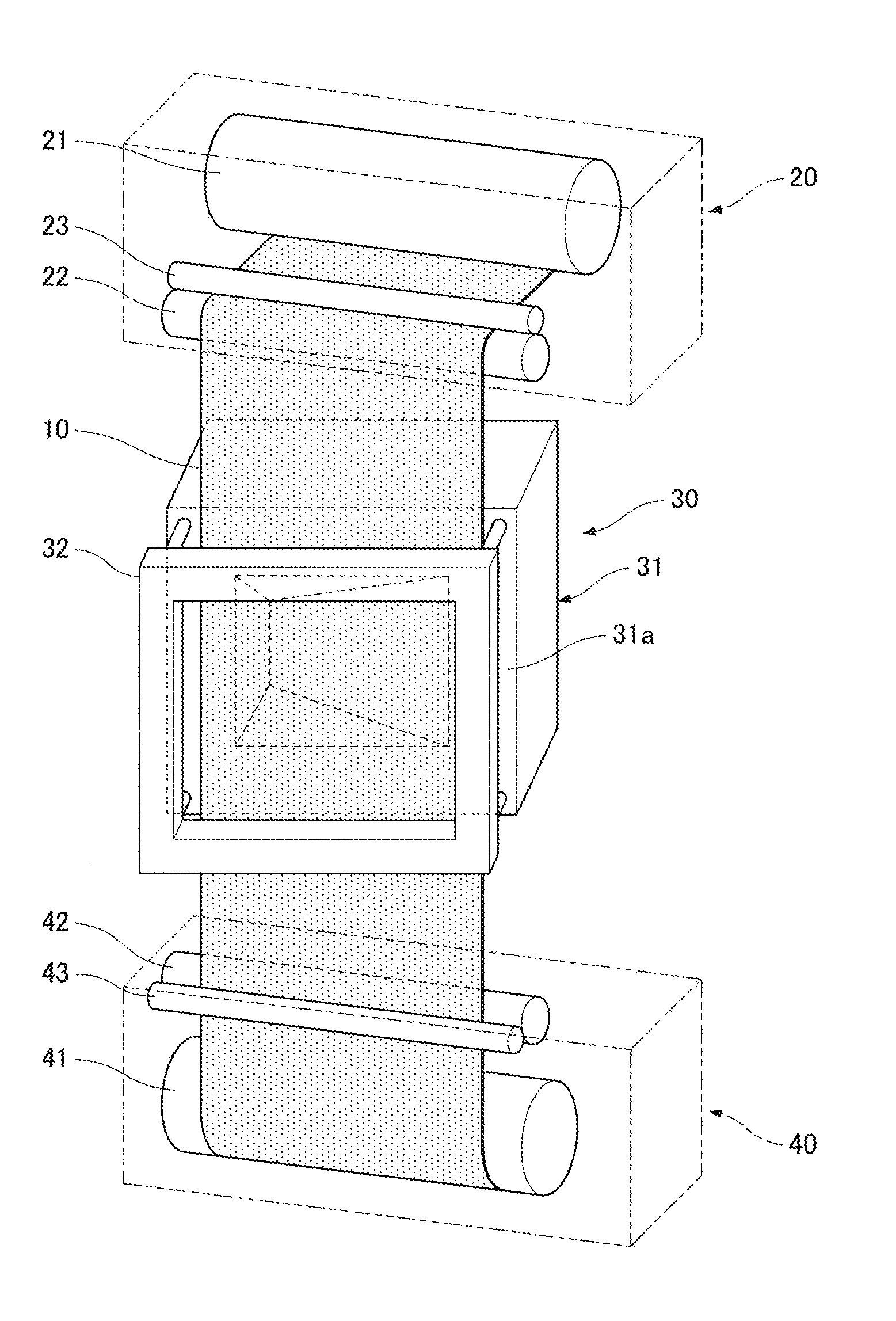
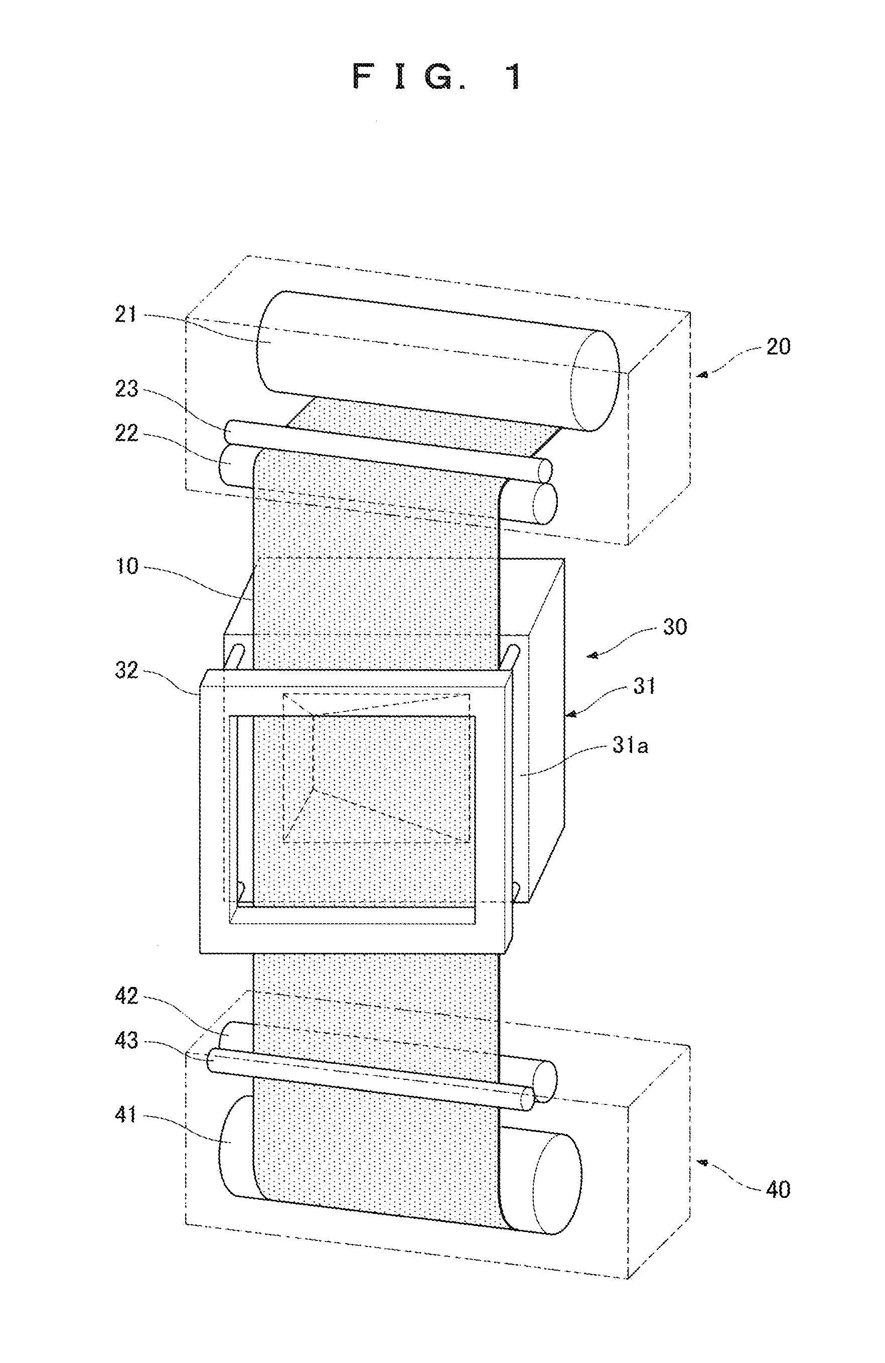
[0061]FIG. 1 is a perspective view schematically illustrating the configuration of an injection molding machine according to the embodiment of the present invention. As shown in FIG. 1, the injection molding machine of the present embodiment is provided with a film feede...


PUM

PropertyMeasurementUnit
depthaaaaaaaaaa
tensionaaaaaaaaaa
tensionaaaaaaaaaa

Abstract

After a first die and a second die are opened, a base film of a film is separated from the first die so as to tilt the surface of the film with respect to a parting face of the first die.

Description

FIELD OF THE INVENTION[0001]The present invention relates to an injection molding method and an injection molding machine that transfer a transfer film, e.g., a decorative film or a functional film to the surface of a molded article while injection-molding the molded article.BACKGROUND OF THE INVENTION[0002]In a known injection molding process, a transfer film, e.g., a decorative film or a functional film is transferred to a molded article during injection molding. The injection molding process typically has the following steps:[0003]First, a film including a base film and a transfer film, e.g., a decorative film or a functional film stacked on the base film is fed between a first die and a second die, which are shaping dies constituting a mold, from the upstream side of the dies. At this point, tension is applied to the film having a flat surface. The surface of the film interposed between the first die and the second die is disposed in parallel with a mold parting face that is the...

Claims


Application Information

Patent Timeline
Patent Type & Authority Applications(United States)
IPC IPC(8): B29C45/14
CPCB29C45/14016B29C45/14065B29C45/14262
Inventor HIRAISHI, MASAKAZUNAKAGAWA, TAKASHIYABE, AKIRA
Owner PANASONIC INTELLECTUAL PROPERTY MANAGEMENT CO LTD
Why Eureka
Try Eureka