Image sensor module

a technology of image sensor and module, applied in the direction of optical radiation measurement, radiation control device, instruments, etc., can solve the problems of difficult to properly incorporate increasing the size of the image sensor module, so as to achieve the effect of compromising rigidity

Inactive Publication Date: 2014-07-17
ROHM CO LTD
View PDF4 Cites 11 Cited by
  • Summary
  • Abstract
  • Description
  • Claims
  • Application Information

AI Technical Summary

Benefits of technology

[0007]The present invention has been proposed in view of the foregoing situation. An object o...

Problems solved by technology

However, locating the sensor IC 96 at a lower position in order to prolong the optical path results in an increase in size of the image sensor module 900 in a t...

Method used


Image

  • Image sensor module
  • Image sensor module
  • Image sensor module

Examples


first embodiment

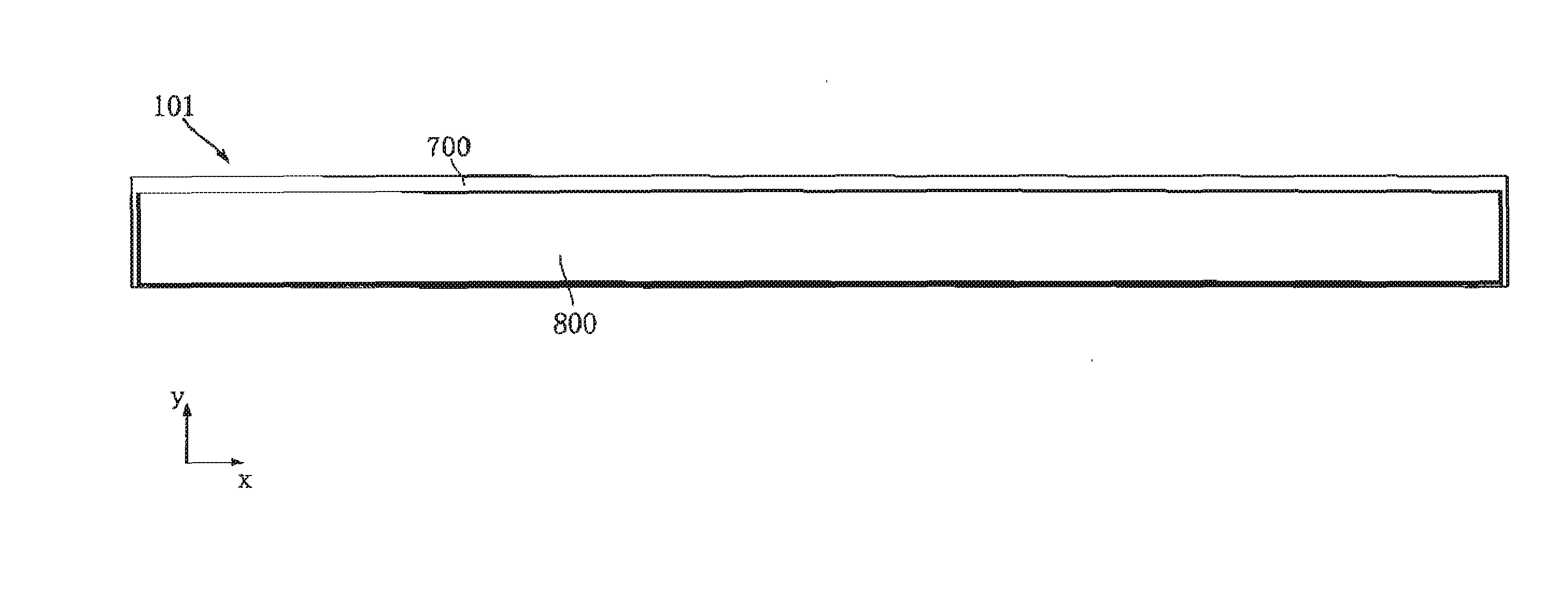
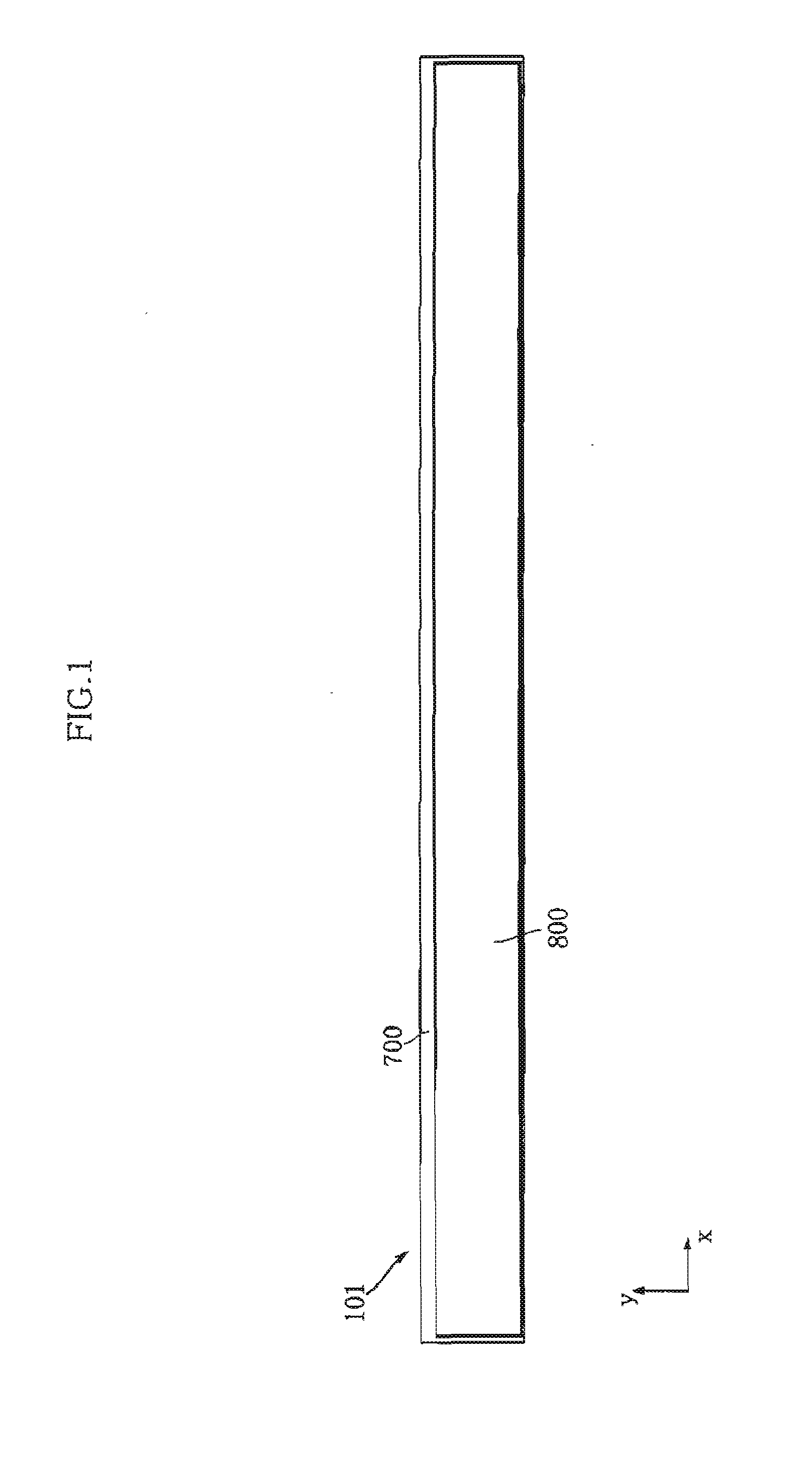
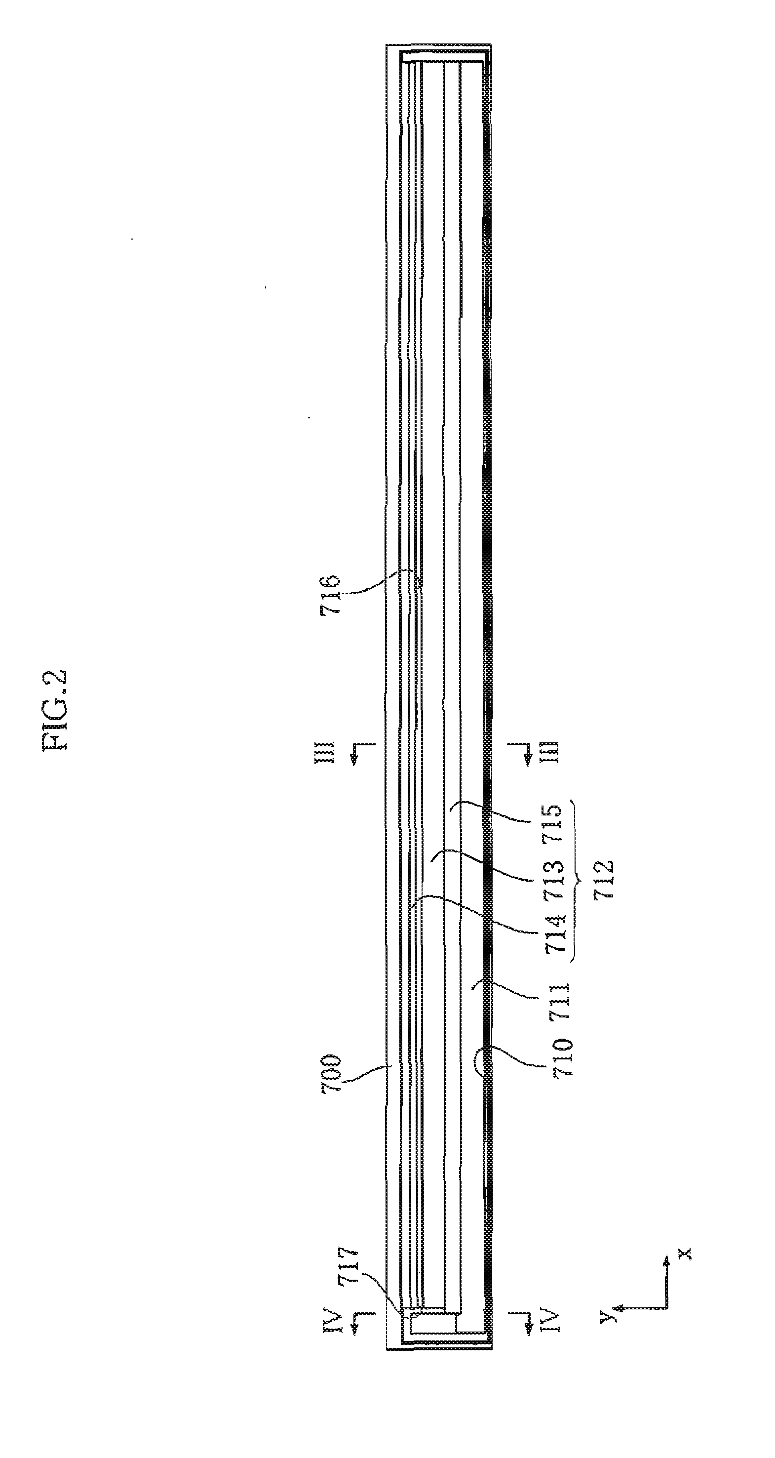
[0101]FIGS. 1, 3, and 4 illustrate an image sensor module according to the present invention. The image sensor module 101 according to this embodiment includes a light source unit 200, a support member 300, a lens unit 400, a sensor IC 500, a substrate 600, a housing 700, and a transmission plate 800. FIG. 2 is a plan view showing the housing 700. FIGS. 3 and 4 are cross-sectional views of the image sensor module 101, and the positions of the respective cutting lines are indicated in FIG. 2. The image sensor module 101 may be incorporated, for example, in a document scanner designed to optically read characters and images printed on an object 890 to be read and generate electronic data containing those characters and images.

[0102]The housing 700 defines the outer shape of the image sensor module 101, and encloses and supports the relevant components. The housing 700 has a thickness direction z orthogonal to both of a primary scanning direction x and a secondary scanning direction y....

second embodiment

[0144]FIGS. 13 and 14 illustrate an image sensor module according to the present invention. The image sensor module 102 according to this embodiment is different from the image sensor module 101 in the shape of the support member 300, and the remaining portions are configured in the same way as the image sensor module 101.

[0145]As shown in FIGS. 13 and 14, the transmissive portion 310 of the support member 300 in this embodiment includes a recessed portion 316, in place of the cavity 314. The recessed portion 316 is formed so as to recede toward the bottom face 311 in the thickness direction z, from the surface of the transmissive portion 310 opposite to the bottom face 311. The recessed portion 316 thus configured can be formed, as shown in FIG. 15, for example by placing the lens unit 400 on the bottom face of the cavity 341 of the mold 340. Such a manufacturing method eliminates the need to use the support pins 342, 352.

third embodiment

[0146]FIGS. 16 and 17 illustrate an image sensor module according to the present invention. The image sensor module 103 shown in FIGS. 16 and 17 is different from the image sensor module 102 in the configuration of the support member 300, and further includes a light shielding member 360. The remaining portions of the image sensor module 103 are configured in the same way as those of the image sensor module 102. FIG. 17 is an enlarged cross-sectional view of the support member 300, the lens unit 400, and the light shielding member 360 extracted from FIG. 16.

[0147]The support member 300 according to this embodiment is formed of a transparent acrylic resin, in generally the same shape as the transmissive portion 310 shown in FIG. 14. The support member 300 according to this embodiment includes a bottom face 301 supported by the housing 700, a sloped surface 302 and a sloped surface 303 inclined with respect to the bottom face 301, and a top face 304 located opposite to the bottom face...


PUM


Abstract

An image sensor module includes a light source unit that emits a linear light beam elongate in a primary scanning direction to an object to be read, and a lens unit including an incidence surface and an output surface oriented opposite to each other. The lens unit is configured to receive light from the object through the incidence surface and output the light through the output surface. The module also includes a sensor IC that receives the light outputted from the output surface, a housing that holds the light source unit and the lens unit, and a support member that supports the lens unit such that the incidence surface is located more distant from the sensor IC than the output surface in a secondary scanning direction. The support member includes a reflection surface that reflects the light from the object toward the incidence surface.

Description

TECHNICAL FIELD[0001]The present invention relates to an image sensor module used for example in a document scanner.BACKGROUND ART[0002]FIG. 38 illustrates an example of conventional image sensor modules. The image sensor module 900 shown in FIG. 38 serves to read a written content of an object to be read 890 transported in a secondary scanning direction y, as image data. The image sensor module 900 includes a housing 91, a substrate 92, an LED module 93, a light guide 94, a lens unit 95, a sensor IC 96, and a transmission plate 97. The housing 91 has an elongate shape extending in a primary scanning direction orthogonal to the secondary scanning direction y and a thickness direction z. The substrate 92 has an elongate rectangular shape extending in the primary scanning direction, and is fitted in the housing 91. The LED module 93 includes a plurality of LED chips 93a, and is located close to an end portion of the housing 91 in the primary scanning direction.[0003]The light guide 94...

Claims


Application Information

Patent Timeline
IPC IPC(8): H04N1/028H04N1/024
CPCH04N1/02481H04N1/0281H04N1/0318H04N2201/03112H04N2201/03154H04N1/02835H04N2201/03125H04N2201/03129H04N2201/03137H04N2201/03141H04N2201/03145H01L27/146G01J1/0411G01J1/44
Inventor MIWA, TADATOSHIYAMADE, TAKUMIARITAKI, YASUYUKINAKAMURA, KUNIAKISEKIGUCHI, NAOKI
Owner ROHM CO LTD
Why Eureka
Try Eureka