

Reciprocating Exhaust Mechanism for Energy Recuperation and Gas Recirculation
- Summary
- Abstract
- Description
- Claims
- Application Information
AI Technical Summary
Benefits of technology
Problems solved by technology
Method used
Image

Examples
Embodiment Construction
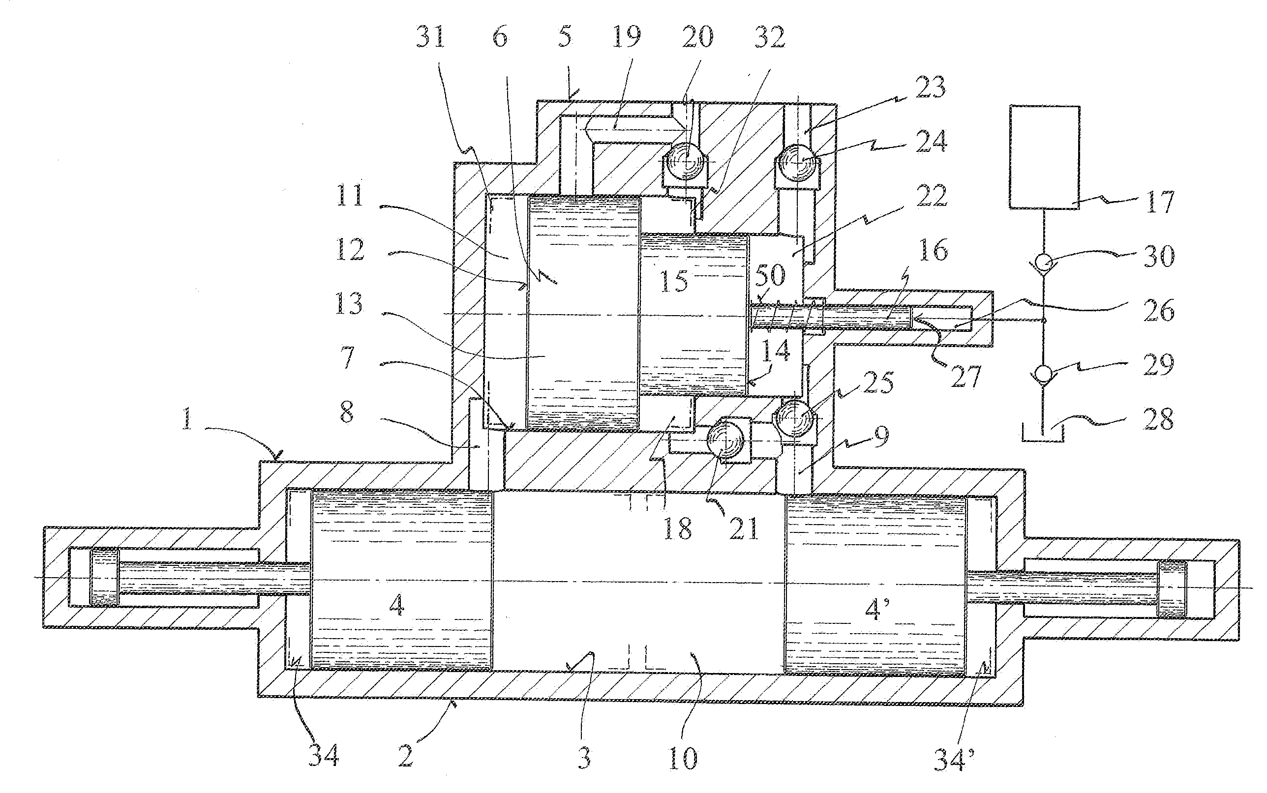
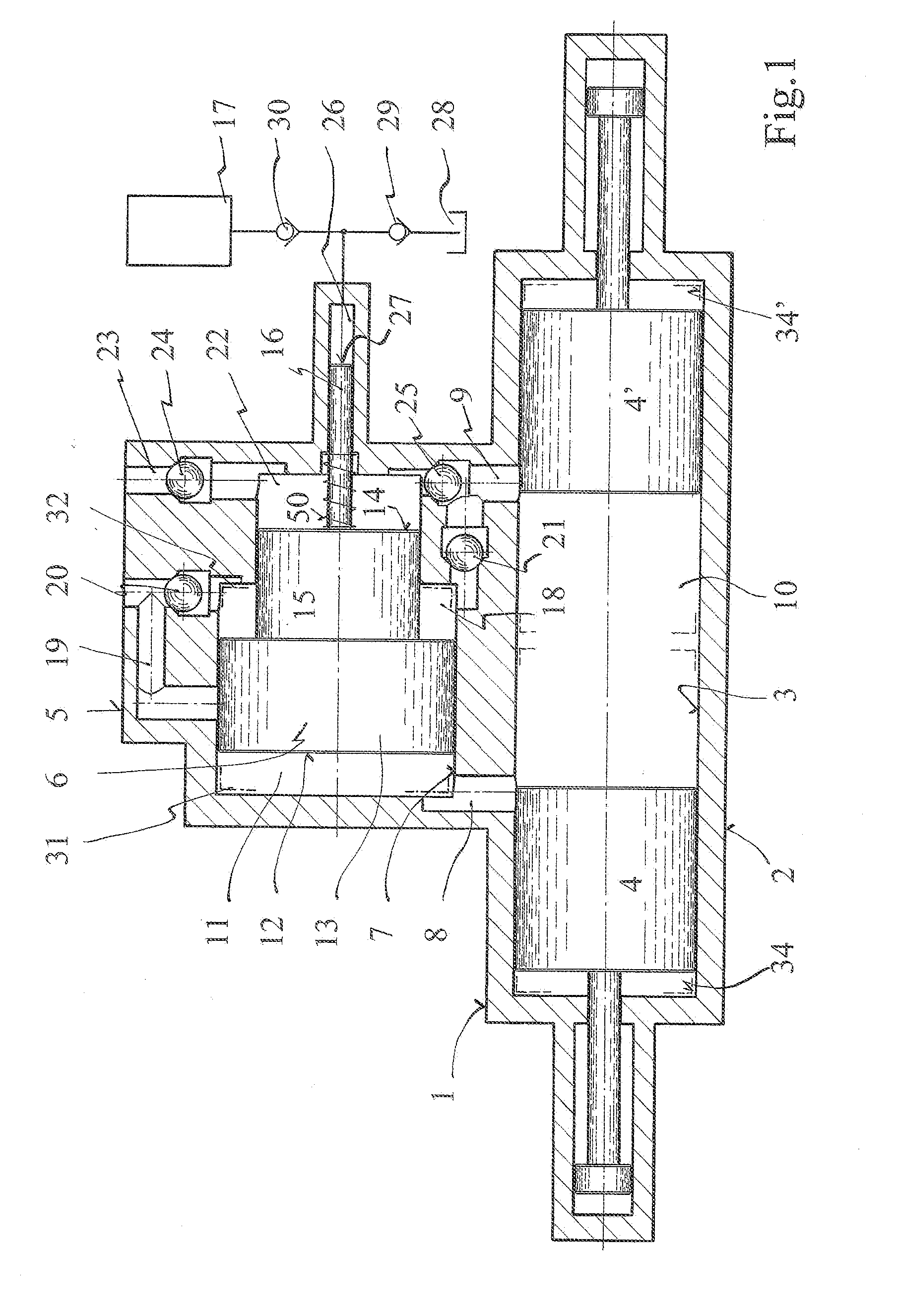
[0023]The exhaust mechanism, shown in FIG. 1, consists of free-piston engine 1, engine housing 2, engine piston bore 3, and a pair of free-pistons 4 and 4′ reciprocably mounted therein. The compound charge mechanism 5, attached to the engine, has a charger piston 6 reciprocally mounted in charger piston bore 7, driven by the exhaust gas pressure from free-piston engine 1. Exhaust port 8 and air intake port 9 provide fluid communication between combustion chamber 10 and charge mechanism 5.
[0024]Piston 4 opens exhaust port 8 providing exhaust gas to chamber 11 and face 12 at air end 13 of charger piston 6 transfers the exhaust gas pressure directly into pressurized fresh air at face 14, pressurized exhaust air at face 15 for charging combustion chamber 10, and pressurized fluid at hydraulic end 16 to be stored in accumulator 17, thus reducing the losses of exhaust gas energy and frictional, and the size and cost of the compound charge mechanism 5.
[0025]Air end 13 having exhaust chambe...
PUM
 Abstract
Description
Claims
Application Information