Shower head unit and chemical vapor deposition apparatus

a technology of chemical vapor deposition and shower head, which is applied in the direction of spray nozzles, coatings, metal material coating processes, etc., can solve the problems of deteriorating product quality, affecting the quality of products, and not being able to uniformly spray reaction gas onto the surface of wafers

Active Publication Date: 2014-07-24
EUGENE TECH CO LTD
View PDF51 Cites 329 Cited by
  • Summary
  • Abstract
  • Description
  • Claims
  • Application Information

AI Technical Summary

Problems solved by technology

In the shower head of the conventional chemical vapor deposition apparatus 1, the spray holes for spraying the reaction gas are not closely arranged so that it is not possible to uniformly spray the reaction gas onto the surface of the wafer.
Therefore, the thin film is not uniformly deposited on the surface of the wafer, which results in deterioration of the quality of products and cause defects in following processes.
As a result, productivity deteriorates.

Method used


Image

  • Shower head unit and chemical vapor deposition apparatus
  • Shower head unit and chemical vapor deposition apparatus
  • Shower head unit and chemical vapor deposition apparatus

Examples


Embodiment Construction

[0020]Hereinafter, preferred embodiments of the present invention will be described with reference to the attached drawings.

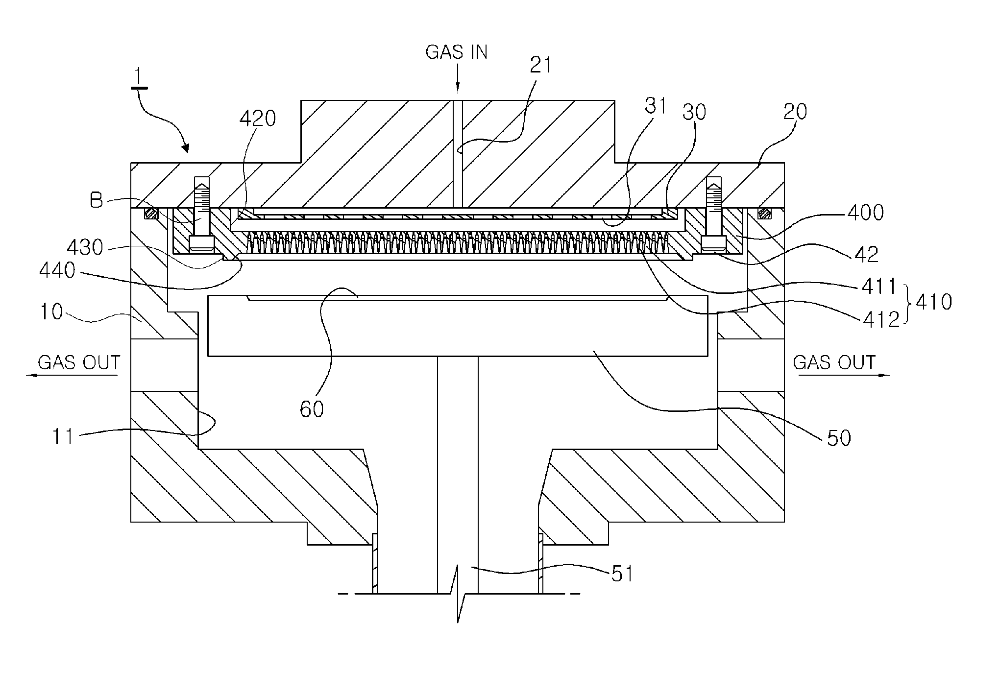
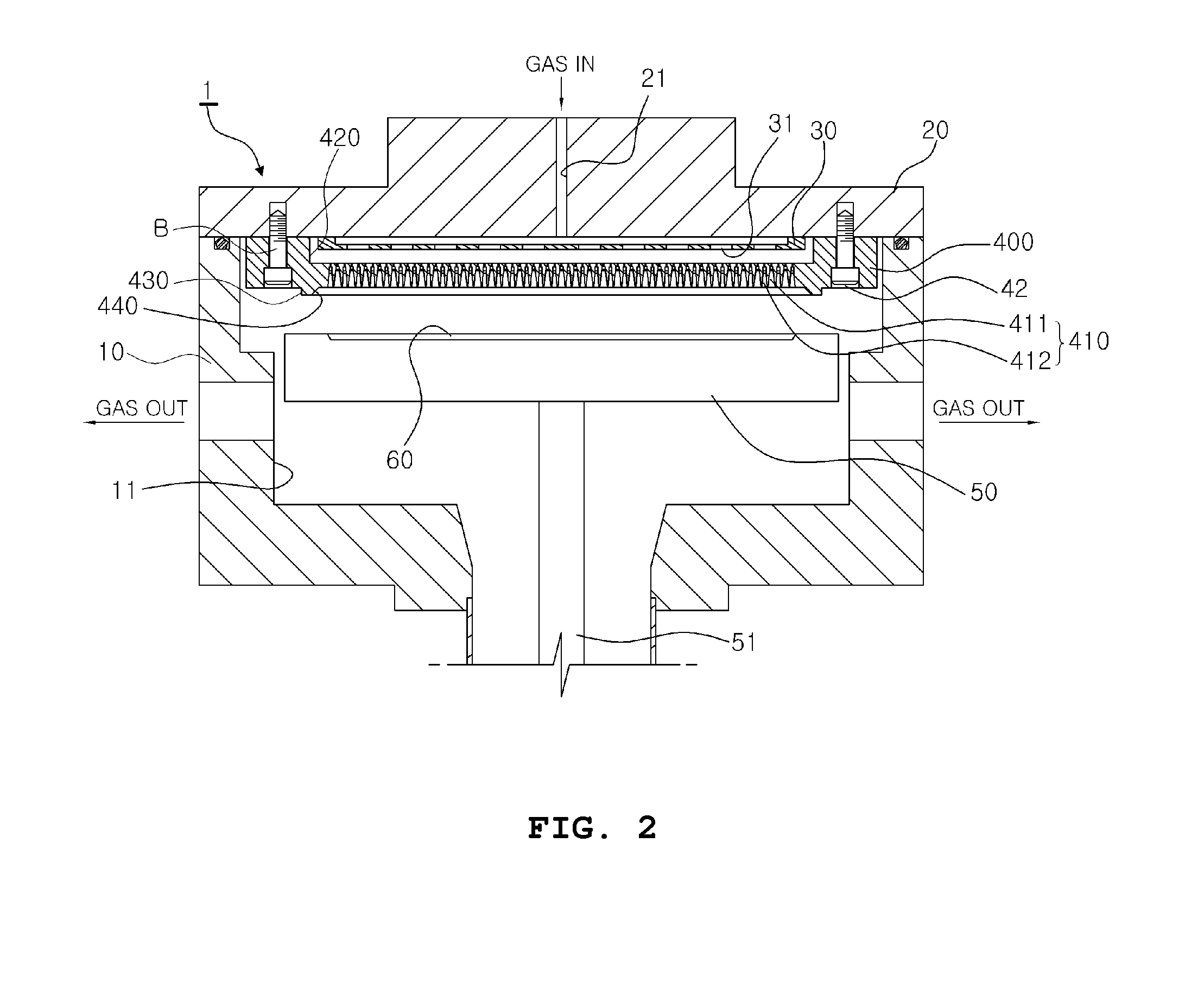
[0021]FIG. 2 is a sectional view of a chemical vapor deposition apparatus 1 according to the present invention. In order to deposit a thin film on the surface of a wafer 60, a reaction gas is flown from a gas in port 21 of a chamber lead 20 and the received reaction gas reaches a block plate 30 that is a low temperature region formed on the bottom surface of the chamber lead 20. At this time, the reaction gas is first distributed by a plurality of through holes 31 formed in the block plate 30 and the distributed reaction gas is flown to main holes 411 and supplementary holes 412 of a shower head 400 fastened to the chamber lead 20 and having an insertion groove 420 to correspond to the block plate 30. The received reaction gas is uniformly sprayed through protrusions 430 formed in the center of the bottom surface of the shower head 400 and an induction groove 4...


PUM

PropertyMeasurementUnit
taper angleaaaaaaaaaa
diameteraaaaaaaaaa
shapeaaaaaaaaaa

Abstract

A chemical vapor deposition apparatus comprises a chamber, a chamber lead having a gas in port configured to receive a reaction gas, the chamber lead connected to a top surface of the chamber to seal up the chamber, a shower head connected to the chamber lead, the shower head having a plurality of spray holes separated from each other for spraying the reaction gas onto the surface of a wafer in the chamber, and a protrusion surrounding the spray holes on the bottom surface of the shower head so that an induction groove is provided inside the protrusion, wherein the plurality of spray holes have a plurality of main holes and a plurality of supplementary holes, each of the main holes is uniformly arranged in each corner of a square-grid pattern across the shower head and each of the supplementary holes is disposed at each centerpoint of the square-grid pattern.

Description

CROSS-REFERENCE TO RELATED APPLICATIONS[0001]This is a Continuation-in-part Application of U.S. application Ser. No. 11 / 573,439, filed on Sep. 30, 2008, which claims the benefit of priority from Korean Patent Application No. 10-2004-0063047, filed on Aug. 11, 2004, the disclosures of both of which are expressly incorporated by reference herein in their entireties.FIELD OF THE INVENTION[0002]The present invention relates to a shower head of a chemical vapor deposition apparatus capable of spraying a process reaction gas (hereinafter, referred to as a reaction gas) on the surface of a semiconductor wafer so that the reaction gas is thermally decomposed on the semiconductor wafer to be deposited on the surface of the semiconductor wafer as a thin film of uniform thickness.DESCRIPTION OF THE RELATED ART[0003]As illustrated in FIG. 1, which is a sectional view of a conventional chemical vapor deposition apparatus 1, the chemical vapor deposition apparatus 1 includes a chamber 10 having a...

Claims


Application Information

Patent Timeline
Patent Type & Authority Applications(United States)
IPC IPC(8): C23C16/455
CPCC23C16/45565
Inventor UM, PYUNG-YONG
Owner EUGENE TECH CO LTD
Why Eureka
Try Eureka