Communication system and communication device

a communication system and communication device technology, applied in the field of communication system and communication device, can solve the problems of difficult relay attack, vehicle including automatic entry function, risk of theft or intrusion,

Inactive Publication Date: 2014-07-24
OMRON AUTOMOTIVE ELECTRONICS CO LTD
View PDF4 Cites 22 Cited by
  • Summary
  • Abstract
  • Description
  • Claims
  • Application Information

AI Technical Summary

Benefits of technology

[0011]One or more embodiments of the present invention makes it difficult to perform a relay attack.

Problems solved by technology

The vehicle including the automatic entry function has a risk of a theft or an intrusion by a technique called a relay attack.
Only when a detection value of the change in intensity of the intensity measuring signal is greater than or equal to a predetermined value, the portable key transmits an answer signal to the in-vehicle communication device, whereby the relay attack is difficult to perform.
Therefore, the relay attack is difficult to perform.
Accordingly, the relay attack may be difficult to perform.
Therefore, the relay attack may be difficult to perform.
Accordingly, the relay attack may be difficult to perform.
Therefore, the relay attack may be difficult to perform.
Accordingly, the relay attack may be difficult to perform.

Method used


Image

  • Communication system and communication device
  • Communication system and communication device
  • Communication system and communication device

Examples


first modification

Modifications Related to Transmission Intensity Pattern

[0336]In the above description, by way of example, the reception intensity is determined while the transmission intensities of both the authentication request signal and the response signal are changed. Alternatively, the reception intensity may be determined while the transmission intensity of one of the authentication request signal and the response signal is changed.

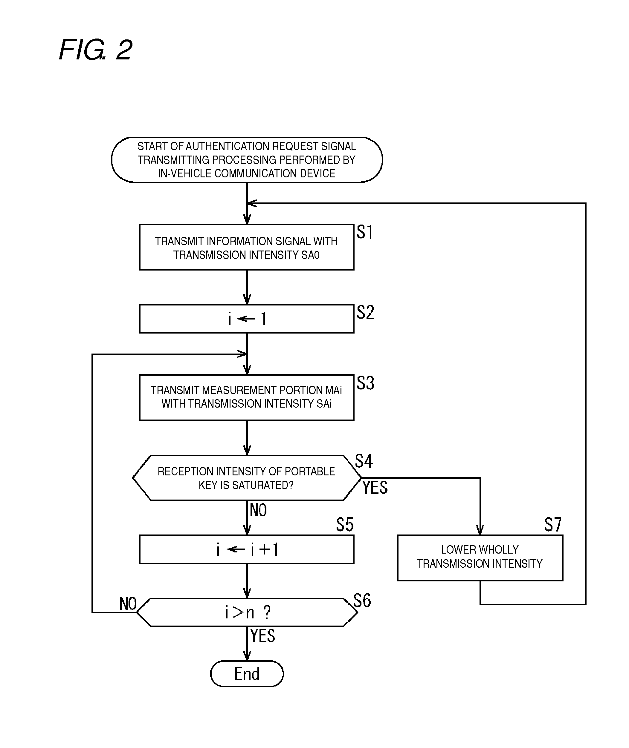
[0337]In the above description, by way of example, the transmission intensity of the measuring signal of the authentication request signal or response signal is changed. Alternatively, the reception intensity may be determined while the transmission intensity of part or whole of the information signal is similarly changed.

[0338]The transmission intensity pattern is not limited to the above examples, but other pattern may be used as long as the patterns are difficult to reproduce in the repeater 104.

second modification

Modifications of Determination Position of Reception Intensity Pattern of Portable Key 112

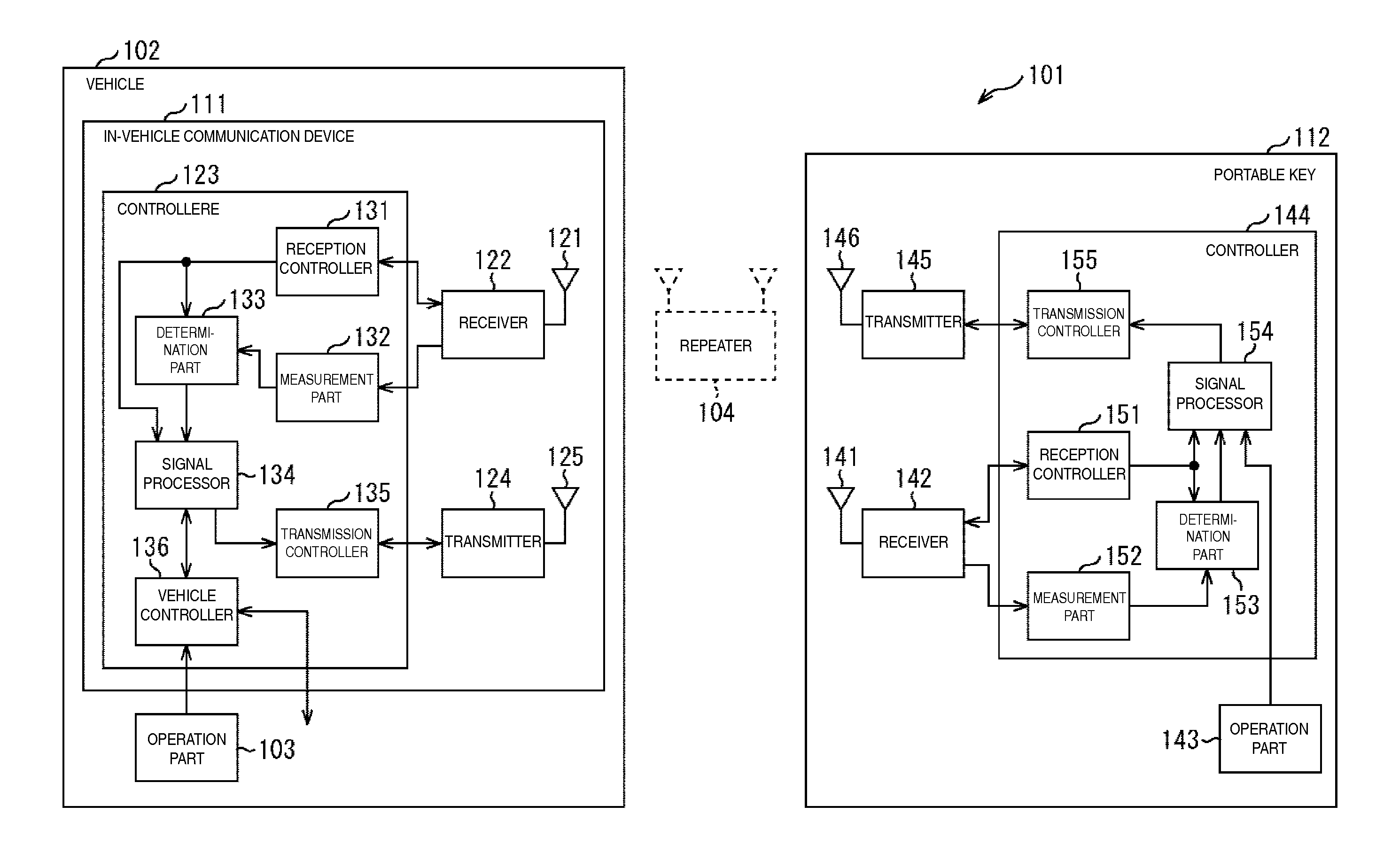
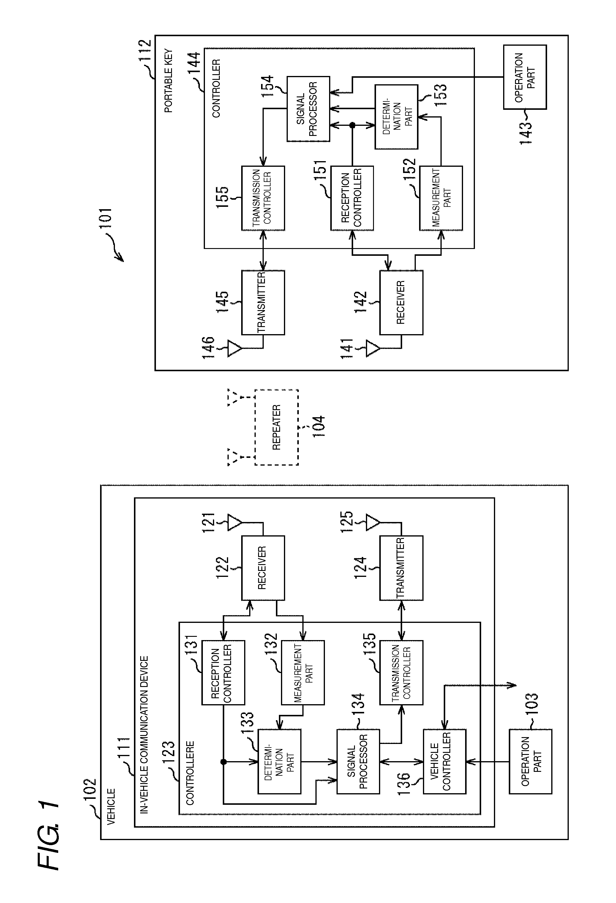
[0339]In the above description, by way of example, the reception-side portable key 112 determines the reception intensity of the portable key 112. Alternatively, the transmission-side in-vehicle communication device 111 may determine the reception intensity of the portable key 112. Pieces of processing in the case that the in-vehicle communication device 111 determines the reception intensity of the portable key 112 will be described below with reference to flowcharts in FIG. 21 to FIG. 24.

[0340](First Embodiment of Processing Performed by in-Vehicle Communication Device 111)

[0341]A first embodiment of the processing performed by the in-vehicle communication device 111 in the case that the in-vehicle communication device 111 determines the reception intensity of the portable key 112 will be described below with reference to the flowchart in FIG. 21.

[0342]For example, the processing is performed...

third modification

Modifications Related to Device Configuration

[0396]The configuration of the in-vehicle communication device 111 is not limited to the example in FIG. 1, but various changes can be made. For example, the reception controller 131 and the transmission controller 135 may be provided outside the controller 123, or the receiver 122 and the transmitter 124 may be provided in the controller 123. For example, the receiver 122 and the reception controller 131 may be combined, or the transmitter 124 and the transmission controller 135 may be combined. For example, the receiver 122 and the transmitter 124 may be combined. In the in-vehicle communication device 111, the portion in which the transmission processing is performed and the portion in which the reception processing is performed may be divided into two devices.

[0397]Similarly, the configuration of the portable key 112 is not limited to the example in FIG. 1, but various changes can be made. For example, the reception controller 151 and...


PUM


Abstract

A communication system has a first communication device, and a second communication device that conducts wireless communication with the first communication device. The first communication device has a first transmitter that transmits a signal to the second communication device, and a first transmission controller that controls the first transmitter. The second communication device has a first receiver that receives the signal from the first communication device, a measurement part that measures a reception intensity of the signal received by the first receiver, and a determination part that determines whether the signal received by the first receiver is a normal signal. The first transmission controller divides a predetermined portion of a predetermined signal into a plurality of portions when transmitting the predetermined signal.

Description

BACKGROUND OF THE INVENTION[0001]1. Technical Field[0002]The present invention relates to a communication system and a communication device, particularly to a communication system and a communication device, which makes a relay attack difficult to perform.[0003]2. Related Art[0004]Nowadays, an electronic key system is popular. The electronic key system includes a function (hereinafter referred to as an automatic entry function) in which a door of a vehicle can be locked and unlocked without using a mechanical key or without operating a portable key by conducting wireless communication between an in-vehicle communication device provided in the vehicle and the portable key possessed by a user.[0005]The automatic entry function is roughly divided into the following two kinds of methods. In the first method, the door of the vehicle is automatically locked and unlocked when a user who possesses the portable key performs a predetermined operation (such that the user touches the door or su...

Claims


Application Information

Patent Timeline
Patent Type & Authority Applications(United States)
IPC IPC(8): G07C9/00
CPCG07C9/00007G07C9/00309G07C2009/00357G07C2009/00555G07C2009/00793G07C9/20
Inventor OHATA, HIROFUMITOMITA, YOSUKEYOSHIZAWA, DAISUKEINAGUMA, TAKAHIROKESSOKU, KENICHIYAMASHITA, SHUJI
Owner OMRON AUTOMOTIVE ELECTRONICS CO LTD
Why Eureka
Try Eureka