Multicast packet control apparatus

a packet control and multi-cast technology, applied in multiplex communication, digital transmission, data switching networks, etc., can solve the problems of increasing the update time of user information, and it is difficult to perform correct user management including accounting services, and achieves high load

Inactive Publication Date: 2007-07-19
HITACHI LTD
View PDF2 Cites 13 Cited by
  • Summary
  • Abstract
  • Description
  • Claims
  • Application Information

AI Technical Summary

Benefits of technology

[0008]When VLANs or PPPOE is used for user management and security management, each of the user terminals and the router are linked in a point-to-point fashion. In multicast communication on that type of network, when a plurality of user terminals receive a join confirmation packet from the multicast router, each user terminal will send a response report packet when a random time elapses. Each user terminal cannot recognize that another user terminal sends a response report, and the multicast router turns out to receive a great number of response report packets simultaneously. In the conventional network, a minimum necessary number of response reports are sent to the multicast router, and the multicast router is protected from excessive load. In the network assumed in the present invention, all the response reports of the user terminals could be sent to the multicast router, and the high load would prevent multicast data from being transferred normally.
[0009]IGMPv2 and the like can disperse, to some extent, the great number of response reports responding to the join confirmation, by increasing the maximum response time value and the cycle of join confirmation by the multicast router. Too great a cycle would increase the user information update time by the multicast router and would make it hard to perform correct user management including an accounting service in some cases.

Problems solved by technology

Too great a cycle would increase the user information update time by the multicast router and would make it hard to perform correct user management including an accounting service in some cases.

Method used


Image

  • Multicast packet control apparatus
  • Multicast packet control apparatus
  • Multicast packet control apparatus

Examples


first embodiment (

3-1. First Embodiment (when Response Reports are Sent Simultaneously)

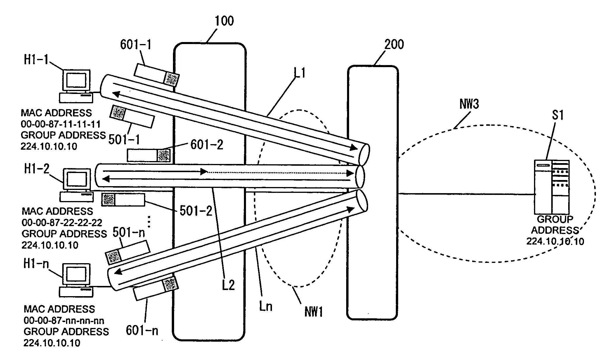
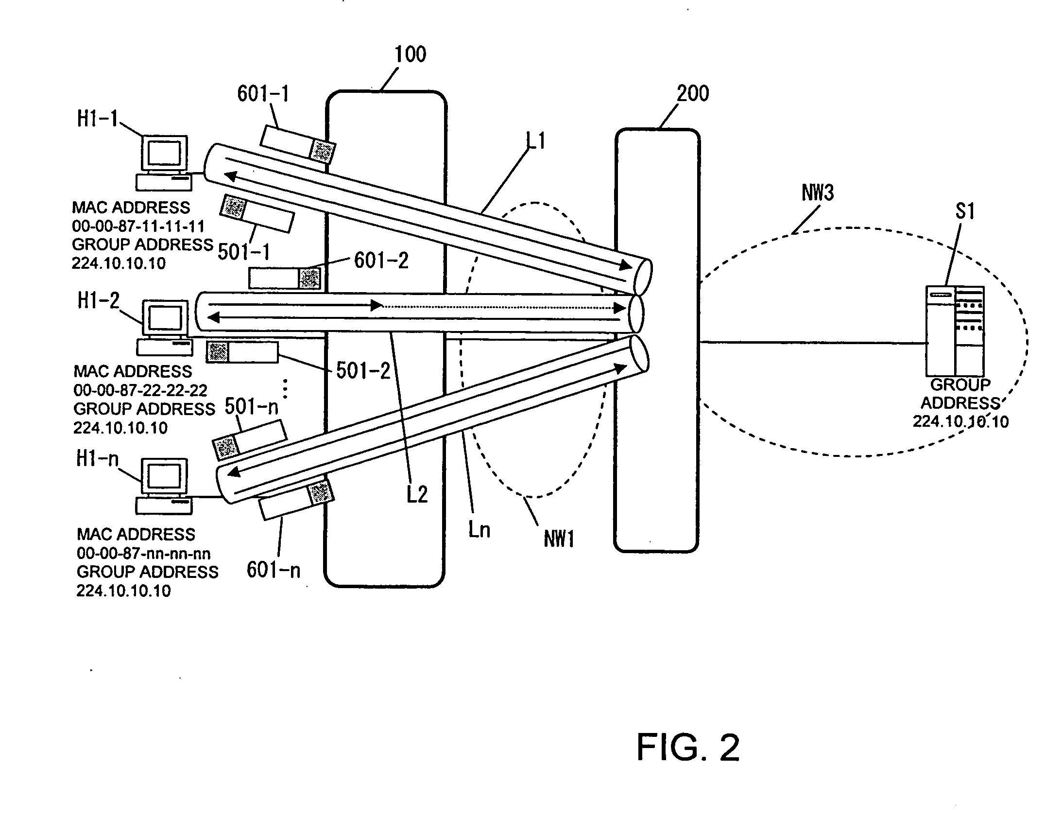
[0097]When the user terminals H1-1 to H1-n return response report packets simultaneously in response to join confirmation made by the router 200, the Layer 2 switch 100 operates as described below.

[0098]The router 200 broadcasts join confirmation packets 500-1 to 501-n to the user terminals H1-1 to H1-n, then the user terminals H1-1 to H1-n return response report packets 601-1 to 601-n simultaneously. The response report packets reach the channel interfaces 100-1 of the Layer 2 switch 100 and are transferred to the channel interface control block 100-2. The channel interface control block 100-2 transfers the received packets to the reception buffer 100-7-2 and makes an interrupt to notify the processor 100-3 that the packets have been received. Receiving the interrupt, the processor 100-3 reads the packets from the reception buffer 100-7-2 and handles the packets in accordance with the flow chart shown in FIG. 13.

[...

second embodiment (

3-2. Second Embodiment (when Join Requests or Leave Statements are Sent Simultaneously)

[0107]Described below will be a case in which the user terminals H1-1 to H1-n send join requests or leave statements simultaneously, independently of join confirmation sent from the router 200.

[0108]The join requests packets 605-1 to 605-n sent simultaneously from the user terminals H1-1 to H1-n are processed in accordance with the flow chart shown in FIG. 14 (in steps 900 to 903). The processor 100-3 checks the transfer limitation table 100-4-1, compares the monitored utilization rate with the value specified in the table, and determines whether a limitation is needed (in step 902) as in the first embodiment. If there are too many packets, packet transfer from the IGMP transmission buffer 100-7-3 to the router 200 is limited (in step 820). The processor 100-3 enlarges the IGMP transmission buffer 100-7-3 in accordance with the transmission buffer size modification table 100-4-3 (in step 821), so ...

third embodiment (

3-3. Third Embodiment (when a Limitation is Imposed on the Group Address Basis)

[0114]FIG. 19 shows that the IGMP transmission buffer 100-7-3 is divided into sections 100-7-3-1 to 100-7-3-n by group address.

[0115]FIG. 20 shows details of the transfer limitation table 100-4-1 with a plurality of group addresses 100-4-1-1 specified. Different values of the IGMP transmission buffer utilization rate 100-4-1-2 and the transfer rate limitation 100-4-1-3 can be specified for the individual group addresses 100-4-1-1.

[0116]FIG. 21 shows details of the transmission buffer size modification table 100-4-3 with a plurality of group addresses 100-4-3-1 specified. Different values of the IGMP transmission buffer utilization rate 100-4-3-2 and the IGMP transmission buffer size 100-4-3-3 can be specified for the individual group addresses 100-4-3-1.

[0117]A case in which transfer limitation processing is performed on the basis of group address in the first embodiment will be described below.

[0118]The ...


PUM


Abstract

When multicast distribution is performed on a network where a point-to-point connection is made between user terminals and a multicast router, the multicast router is protected from load due to response reports, join requests, or leave statements sent from the user terminals simultaneously. If the user terminals send response reports simultaneously, a Layer 2 switch disposed between the user terminals and the multicast router limits response reports sent to the multicast router. The Layer 2 switch prevents response reports sent from the same user terminal from being discarded consecutively, by sending a response report sent from the same user terminal to the multicast router 200 with priority in the next join confirmation event. If the user terminals send join requests or leave statements simultaneously, the Layer 2 switch limits the join requests or leave statements sent to the multicast router 200 in the same manner. The Layer 2 switch further enlarges a transmission buffer thereof at the multicast router side, so that the packets can be stored in the buffer.

Description

BACKGROUND OF THE INVENTION[0001]1. Field of the Invention[0002]The present invention relates to multicast packet control apparatuses for use in content information distribution such as broadcasting, and more specifically, to a multicast packet control apparatus for transferring a response report, a join request, and a leave statement.[0003]2. Description of the Related Art[0004]Use of broadband has brought multicast technologies for content distribution such as broadcasting into spotlight. Efficient information distribution can be performed by using a router and an access server supporting IP multicasting for implementing a broadcast service on an Internet Protocol (IP) network built for communication. The Internet Engineering Task Force (IETF) has specified Internet Group Membership Protocol (IGMP) protocols (RFC 1112 and RFC 2236) for IPv4 and a Multicast Listener Discovery (MLD) protocol (RFC 2710) for IPv6, as standard TCP / IP technologies related to multicast communication for ...

Claims


Application Information

Patent Timeline
Patent Type & Authority Applications(United States)
IPC IPC(8): H04L12/56H04L12/46H04L47/6275
CPCH04L12/1881
Inventor IKEGAMI, KOZOYOKOYAMA, TAKASHINAGAI, MINORUSAKAMOTO, YOSHITAKAONIZAWA, SHIGEHIRO
Owner HITACHI LTD
Why Eureka
Try Eureka