Unlock instant, AI-driven research and patent intelligence for your innovation.

Timing signal generating device, electronic apparatus, moving object, method of generating timing signals, and method of controlling satellite signal receiver

Active Publication Date: 2014-07-24
MICROCHIP TECH INC
View PDF14 Cites 19 Cited by
  • Summary
  • Abstract
  • Description
  • Claims
  • Application Information

AI Technical Summary

Benefits of technology

The invention provides a device, method, and system for generating accurate timing signals, even when the signal receiver is in a moving or unfixed location. This avoids the limitations of current technology and reduces costs. The method uses positioning information from a first mode to calculate the position in a second mode, allowing for greater flexibility and cost savings.

Problems solved by technology

In contrast, in a situation in which the reception environment of satellite signals is too poor for receiving satellite signals from many GPS satellites, precision of position information of positioning results and 1 PPS is deteriorated.
However, there are problems that, in the former case, it may be difficult to acquire position information depending on the receiving location and, in the latter case, costs including expense and time may be required.
However, in the case where some error such as multipath occurs, position information as a result of positioning calculation contains a significant error.
Accordingly, in the method of Patent Document 1 of averaging results of positioning calculation, an error of the position of the receiving point obtained as the averaging result may be significant.
On this account, in the method of Patent Document 1, there is a problem that the precision of 1 PPS (timing signal) may be deteriorated depending on the reception environment for positioning calculation.
The problem is a common problem not only for the GPS receiver but for receiving devices of other global navigation satellite systems (GLASS).
When the reception environment of the satellite signals is deteriorated, errors of the positioning calculation due to multipath or the like become significant.
If the mean value of the positioning results is set as the position information in the second mode as in the method of related art, it is highly likely that the errors are significant.
However, the mode value or the median value is set as in the application example and the positioning results with significant errors hardly have an effect, and thereby, the accurate timing signals may be generated compared to the method of related art.
Thus, the positioning results with significant errors hardly have an effect, and the accurate timing signals may be generated compared to the method of related art.

Method used


Image

  • Timing signal generating device, electronic apparatus, moving object, method of generating timing signals, and method of controlling satellite signal receiver
  • Timing signal generating device, electronic apparatus, moving object, method of generating timing signals, and method of controlling satellite signal receiver
  • Timing signal generating device, electronic apparatus, moving object, method of generating timing signals, and method of controlling satellite signal receiver

Examples


first embodiment

1-1. First Embodiment

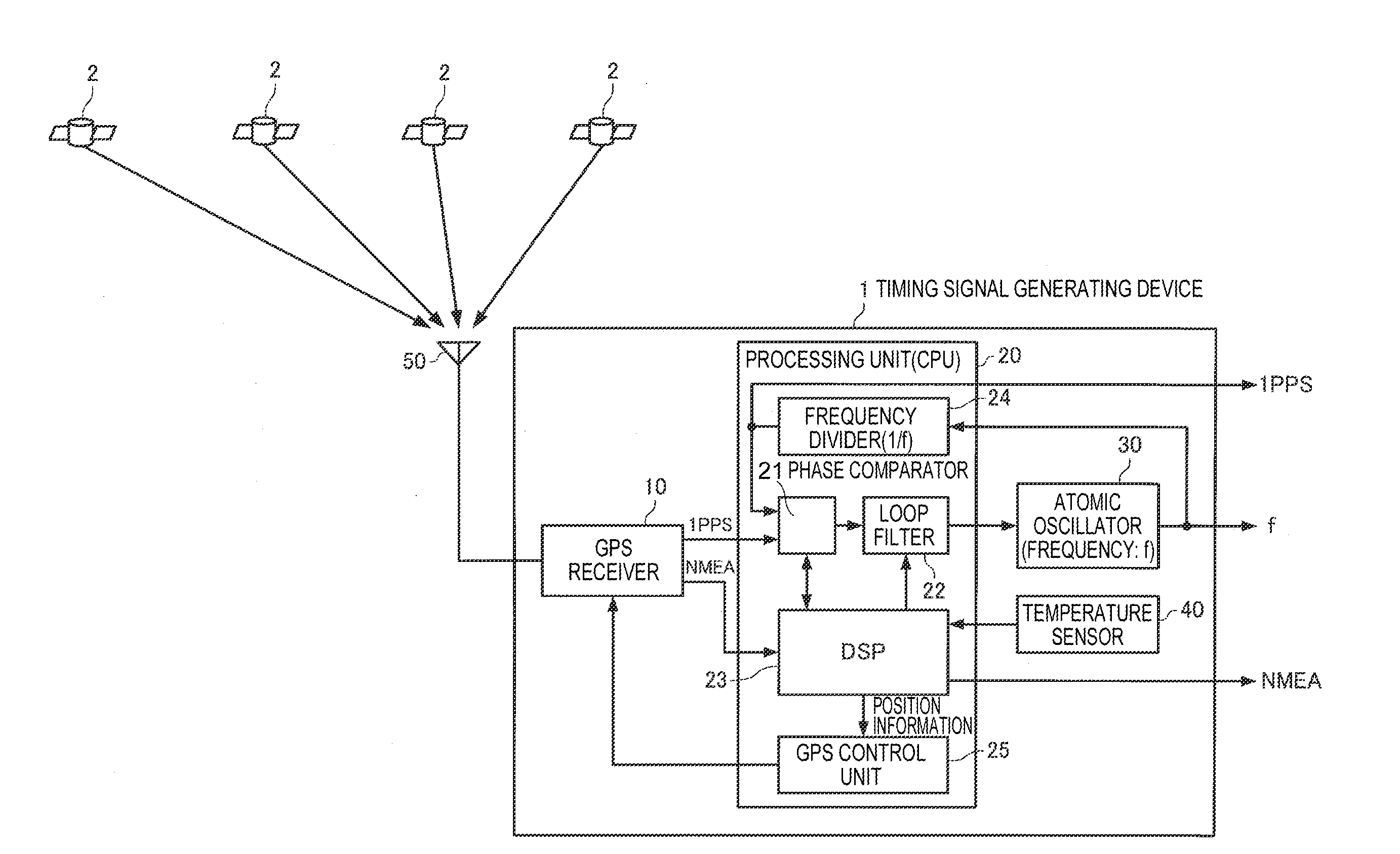
[0051]FIG. 1 shows a configuration example of a timing signal generating device of a first embodiment. As shown in FIG. 1, a timing signal generating device 1 of the first embodiment includes a GPS receiver 10, a processing unit (CPU) 20, an atomic oscillator 30, a temperature sensor 40, and a GPS antenna 50. Note that the timing signal generating device 1 of the embodiment may have a configuration in which part of these elements is omitted or changed or another element is added. Further, the timing signal generating device 1 of the embodiment may have a configuration in which part or all of the component elements may be physically separated or integrated. For example, the GPS receiver 10 and the processing unit (CPU) 20 may be respectively realized by separate ICs or the GPS receiver 10 and the processing unit (CPU) 20 may be realized as a single-chip IC.

[0052]As will be described later in detail, the timing signal generating device of the embodiment receives s...

second embodiment

1-2. Second Embodiment

[0114]FIG. 8 shows a configuration example of a timing signal generating device of a second embodiment. As shown in FIG. 8, the timing signal generating device 1 of the second embodiment includes two GPS receivers 10A, 10B, the processing unit (CPU) 20, the atomic oscillator 30, the temperature sensor 40, and two GPS antennas 50A, 50B. Note that the timing signal generating device 1 of the embodiment may have a configuration in which part of these elements is omitted or changed or another element is added.

[0115]As shown in FIG. 8, the GPS antenna 50A is connected to the GPS receiver 10A, and the GPS receiver 10A receives satellite signals transmitted from the respective GPS satellites 2 via the GPS antenna 50A and performs various kinds of processing explained in the first embodiment. Similarly, the GPS antenna 50B is connected to the GPS receiver 10B, and the GPS receiver 10B receives the satellite signals transmitted from the respective GPS satellites 2 via t...

third embodiment

1-3. Third Embodiment

[0131]FIG. 10 shows a configuration example of a timing signal generating device of a third embodiment. As shown in FIG. 10, the timing signal generating device 1 of the third embodiment includes three GPS receivers 10A, 10B, 10C, the processing unit (CPU) 20, the atomic oscillator 30, the temperature sensor 40, and three GPS antennas 50A, 50B, 50C. Note that the timing signal generating device 1 of the embodiment may have a configuration in which part of these elements is omitted or changed or another element is added.

[0132]As shown in FIG. 10, the GPS antenna 50A is connected to the GPS receiver 10A, and the GPS receiver 10A receives satellite signals transmitted from the respective GPS satellites 2 via the GPS antenna 50A and performs various kinds of processing explained in the first embodiment. Similarly, the GPS antenna 50B is connected to the GPS receiver 10B, and the GPS receiver 10B receives the satellite signals transmitted from the respective GPS sate...


PUM


Abstract

A timing signal generating device includes a GPS receiver and a processing unit. The GPS receiver functions as a positioning calculation unit, and receives satellite signals transmitted from GPS satellites and performs positioning calculation based on trajectory information and time information contained in the received satellite signals. Further, the processing unit functions as a position information generation unit, and generates position information of a receiving point based on a mode value or a median value in results of the positioning calculation at a plurality of times by the GPS receiver.

Description

BACKGROUND[0001]1. Technical Field[0002]The present invention relates to a timing signal generating device, an electronic apparatus, a moving object, a method of generating timing signals, and a method of controlling a satellite signal receiver.[0003]2. Related Art[0004]GPS (Global Positioning System) as one of global navigation satellite systems (GNSS) using artificial satellites have been widely known. An extremely high precision atomic clock is mounted on a GPS satellite and transmits satellite signals on which trajectory information, accurate time information of the GPS satellite, etc. are superimposed to the ground. A GPS receiver receives the satellite signals transmitted from the GPS satellites, and performs processing of calculating a current position and a current time based on the trajectory information and the time information superimposed on the satellite signals, processing of generating accurate timing signals in which time is updated every second (1 PPS), etc.[0005]Th...

Claims


Application Information

Patent Timeline
IPC IPC(8): G01S19/13
CPCG01S19/13G01S19/06G01S19/256G01S19/14G04F5/145G04R40/02
Inventor SHIMADA, HIROYUKIMAKI, YOSHIYUKITANAKA, NORIAKI
Owner MICROCHIP TECH INC