Reflective liquid crystal display device and electronic apparatus provided therewith

a liquid crystal display and display device technology, applied in static indicating devices, instruments, non-linear optics, etc., can solve the problems of increased thickness of apparatus or devices, increased manufacturing costs, and restricted improvement of display contrast, so as to improve flexibility in designing the optical system of reflective liquid crystal display devices and simplify the device structure. , the effect of improving the contrast of the display

Active Publication Date: 2014-07-24
JAPAN DISPLAY INC
View PDF4 Cites 11 Cited by
  • Summary
  • Abstract
  • Description
  • Claims
  • Application Information

AI Technical Summary

Benefits of technology

[0011]In the reflective liquid crystal display device having the aforementioned structure, and the electronic apparatus provided with such a reflective liquid crystal display device, a phase difference is obtained by the anisotropic scattering member. Thereby, the view angle is compensated, and the display contrast is improved. Furthermore, the flexibility in designing an o

Problems solved by technology

However, there is a restriction in improving the display contrast, because of a view angle characteristic of the liquid crystal.
However, a number of layers i

Method used


Image

  • Reflective liquid crystal display device and electronic apparatus provided therewith
  • Reflective liquid crystal display device and electronic apparatus provided therewith
  • Reflective liquid crystal display device and electronic apparatus provided therewith

Examples


Embodiment Construction

[0047]The present disclosure will now be described according to the following orders and with reference to the accompanying drawings.

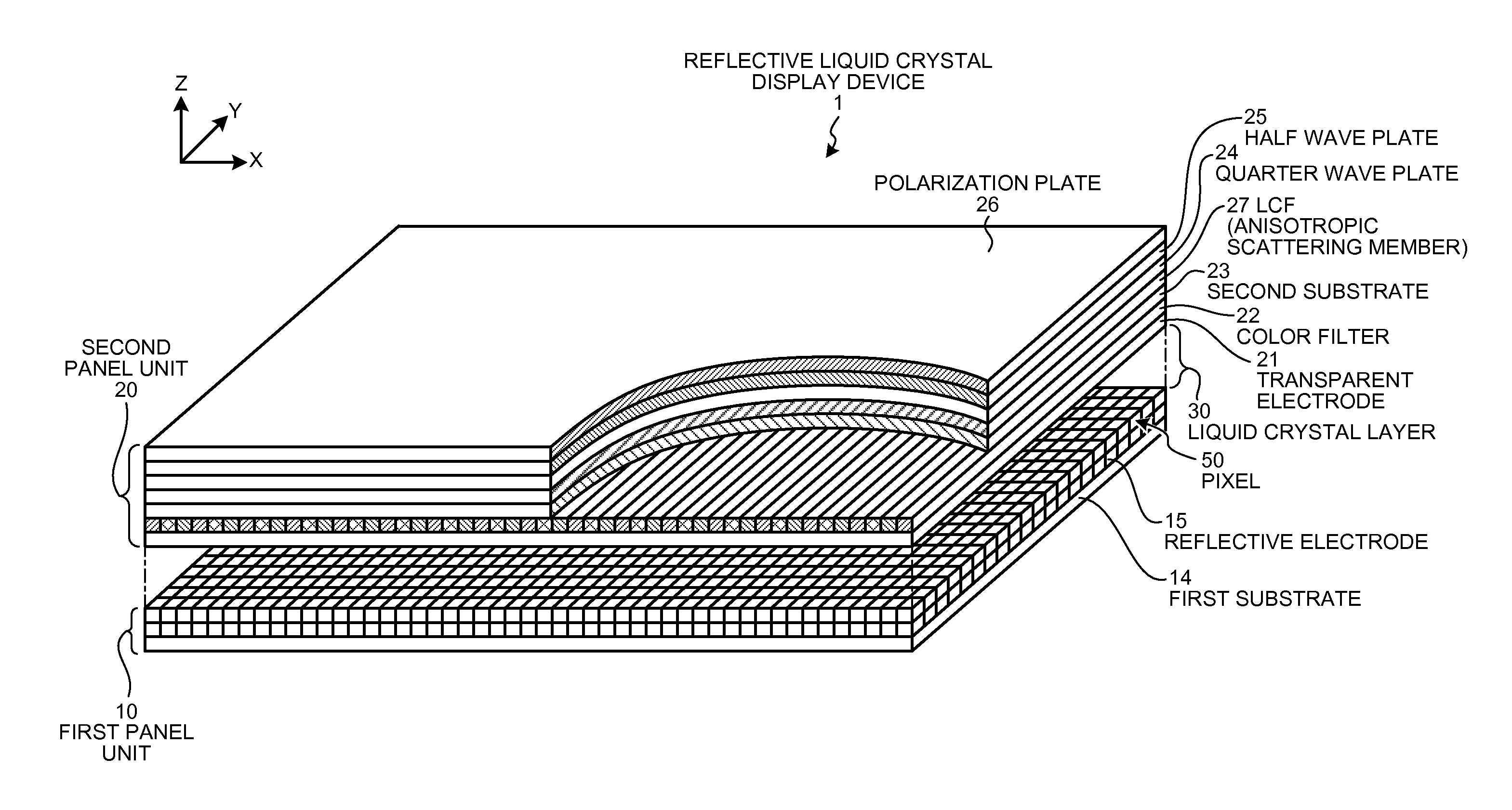
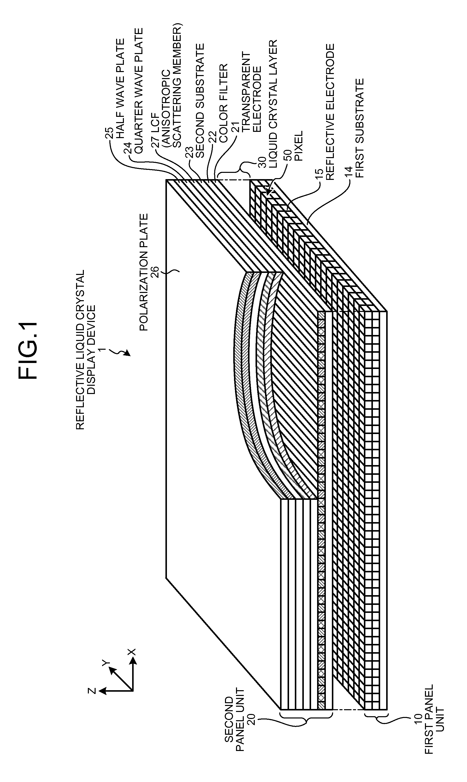
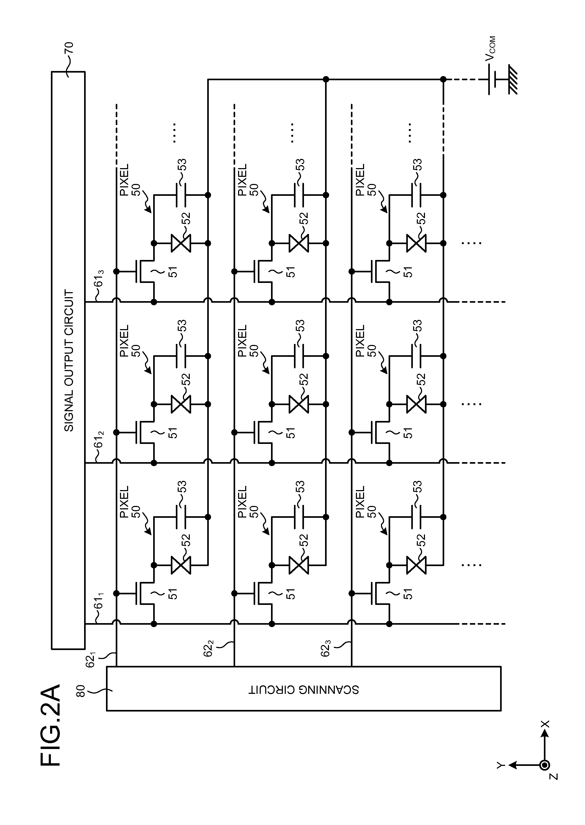
[0048]1. Reflective LCD Device[0049]1-1. Reflective LCD Device for Color Display[0050]1-2. Fundamental Pixel Circuit[0051]1-3. Pixel and Sub-pixel[0052]1-4. Electrode Structure of Pixel portion[0053]1-5. Driving Scheme of LCD Panel[0054]1-6. Anisotropic Scattering Member

[0055]2. Electronic Apparatus

[0056]3. Configuration of Present Disclosure

[0057]

[0058]A technology in the present disclosure can be applied to a flat panel type display device. Examples of the flat panel type display device includes a display device using a liquid crystal display (LCD) panel, a display device using electro luminescence (EL) display panel, a display panel using a plasma display (PD) panel, and so on.

[0059]These flat panel type display devices can be classified into transmissive type and reflective type, according to display schemes. The technology in the present disclosur...


PUM


Abstract

A reflective liquid crystal display device includes a first substrate provided with a reflective electrode, a second substrate provided with a transparent electrode, a liquid crystal layer disposed between the first substrate and the second substrate, and an anisotropic scattering member formed on the second substrate. The anisotropic scattering member has first and second surfaces each including a first refractive index region and a second refractive index region having a refractive index different from that of the first refractive index region. A refractive index difference between the first refractive index region and the second refractive index region in the first surface is larger than that in the second surface. The anisotropic scattering member is disposed so that light enters from the first surface thereof and the light exits as scattered light from the second surface thereof. A phase difference is given to the light entered the anisotropic scattering member.

Description

CROSS REFERENCES TO RELATED APPLICATIONS[0001]The present application claims priority to Japanese Priority Patent Application JP 2013-011226 filed in the Japan Patent Office on Jan. 24, 2013, the entire content of which is hereby incorporated by reference.BACKGROUND[0002]1. Field of the Invention[0003]The present invention relates to a reflective liquid crystal display (LCD) device and an electronic apparatus provided therewith.[0004]2. Description of the Related Art[0005]As a display device, there is known a reflective type display device for displaying an image using reflected light of incident light entered from outside, as well as a transmissive type display device for displaying an image using transmitted light of backlight from a rear surface of a screen. The reflective type display device has advantageous features such as low power consumption and viewable screen or monitor even in bright environment.[0006]Furthermore, there is known a reflective type display device in which ...

Claims


Application Information

Patent Timeline
IPC IPC(8): G02F1/1335
CPCG02F1/133504G02F1/133553G02F1/13306G02F1/133514G02F1/133528G02F1/13363G02F1/134336G02F1/13439G02F1/136286G02F1/1368G02F1/137G02F2201/123G02F2203/02G02F2203/03G02F2413/02G02F2413/06G02F1/133357G02F1/133638G02F1/134345
Inventor MITSUI, MASASHIFUKUNAGA, YOKO
Owner JAPAN DISPLAY INC
Why Eureka
Try Eureka