Cable assembly backshell

a backshell and cable technology, applied in the direction of coupling device connection, optical elements, instruments, etc., can solve the problems of limiting the usefulness of the device, increasing the cost of inventory and storage space, and design further complicating the problem of inventory and control, so as to reduce the requirement of inventory and improve the effect of efficiency

Active Publication Date: 2014-07-24
R KERN ENG & MFG
View PDF2 Cites 10 Cited by
  • Summary
  • Abstract
  • Description
  • Claims
  • Application Information

AI Technical Summary

Benefits of technology

[0009]Embodiments of the present invention contemplate a novel cable assembly backshell that has two rotatable joints. Thus, efficiency is improved by reducing inventory requirements as the backshell can be reconfigured and adjusted in the field to fit several standard angular configurations. The cable assembly backshell is generally comprised of a connector piece, a cable entry piece, and a union piece that interconnects the connector and cable entry pieces. The connector piece and the cable entry piece each have one end angled at approximately 22.5° and one straight end. The union piece has two ends angled at approximately 22.5°. The angled ends of the connector piece and the cable entry piece are each rotatably interconnected to the angled ends of the union piece to form two rotatable joints. By rotating the connector piece and the cable entry piece, the straight ends of the backshell can be positioned in four configurations: a straight configuration, two 45° configurations, and a 90° configuration. The present invention also generally relates to other areas of the electrical connection field such as d-subminiature connectors and other rectangular connector fields that may utilize the multi-angular connectors of the present invention.

Problems solved by technology

However, angled backshells produced in these standard configurations are generally not interchangeable which limits their usefulness.
Further, suppliers must stock backshells for each type of connector (copper cable or fiber optic cable) and entry angle, which increases inventory costs and storage space requirements.
Although the adapter of this design may allow the backshell to be used in various angles, the design further complicates inventory and control problems by using small, loose adapters of various angles and sizes.
Further, the small adapters can be inadvertently introduced into the electrical component by the technician, which may cause damage to the component.
Identification and removal of misplaced adapters from electrical components can be difficult and time consuming, further negatively impacting efficiency.
However, when the backshell is pivoted, the contained cable may be bent sharply and therefore these pivoting backshells may not be suitable for use with some types of cables.
In addition, these backshells only articulate in one plane, which limits their use.
The backshells also fail to fully protect the cable which may be exposed within the pivot arms unless a separate shield is utilized over this area.
However, because this backshell has only one rotating joint, some intended cable installations may not be possible.
Therefore, this rotating backshell is not suitable for some types of electrical or fiber optic cables.

Method used


Image

  • Cable assembly backshell
  • Cable assembly backshell
  • Cable assembly backshell

Examples


Embodiment Construction

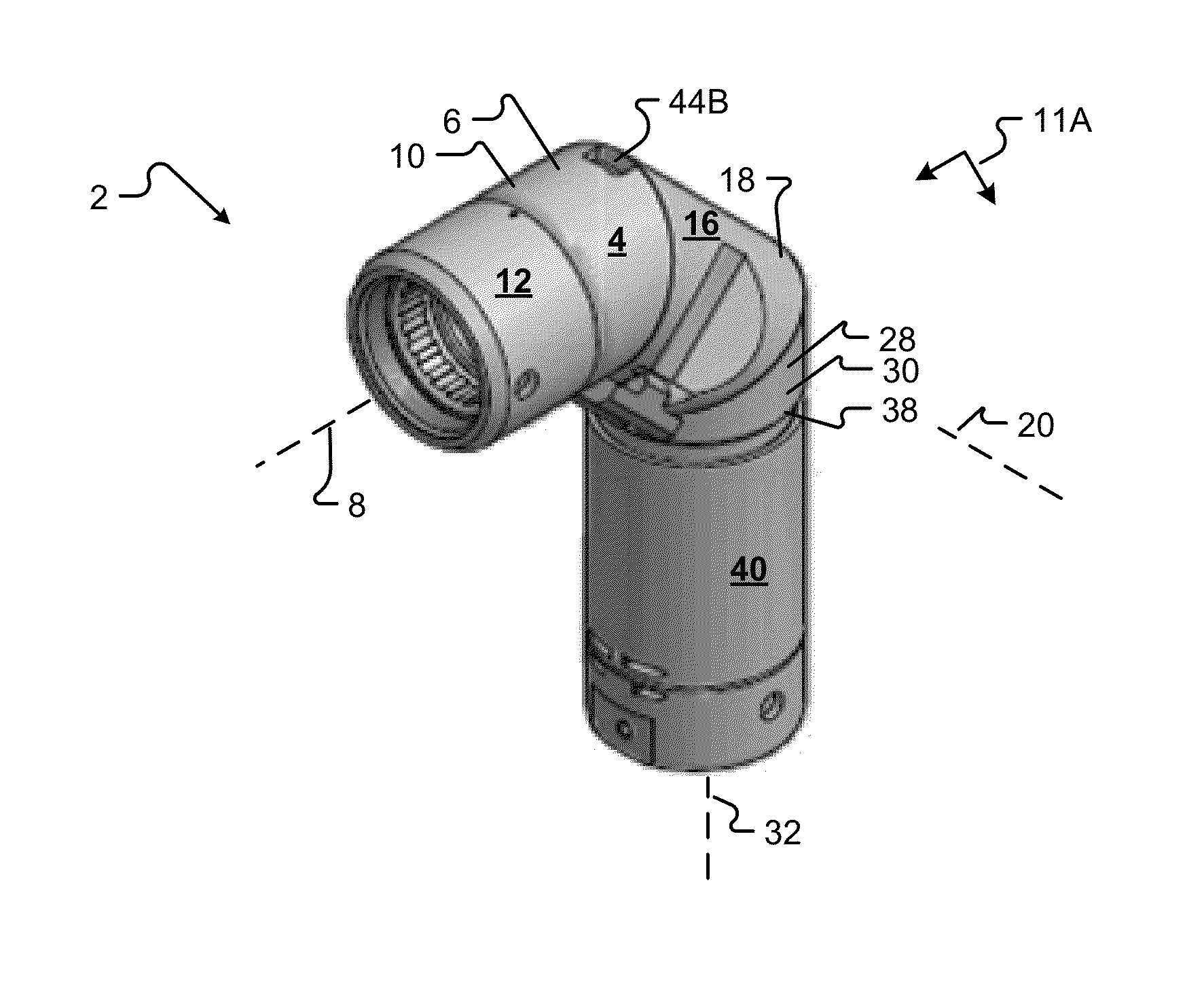
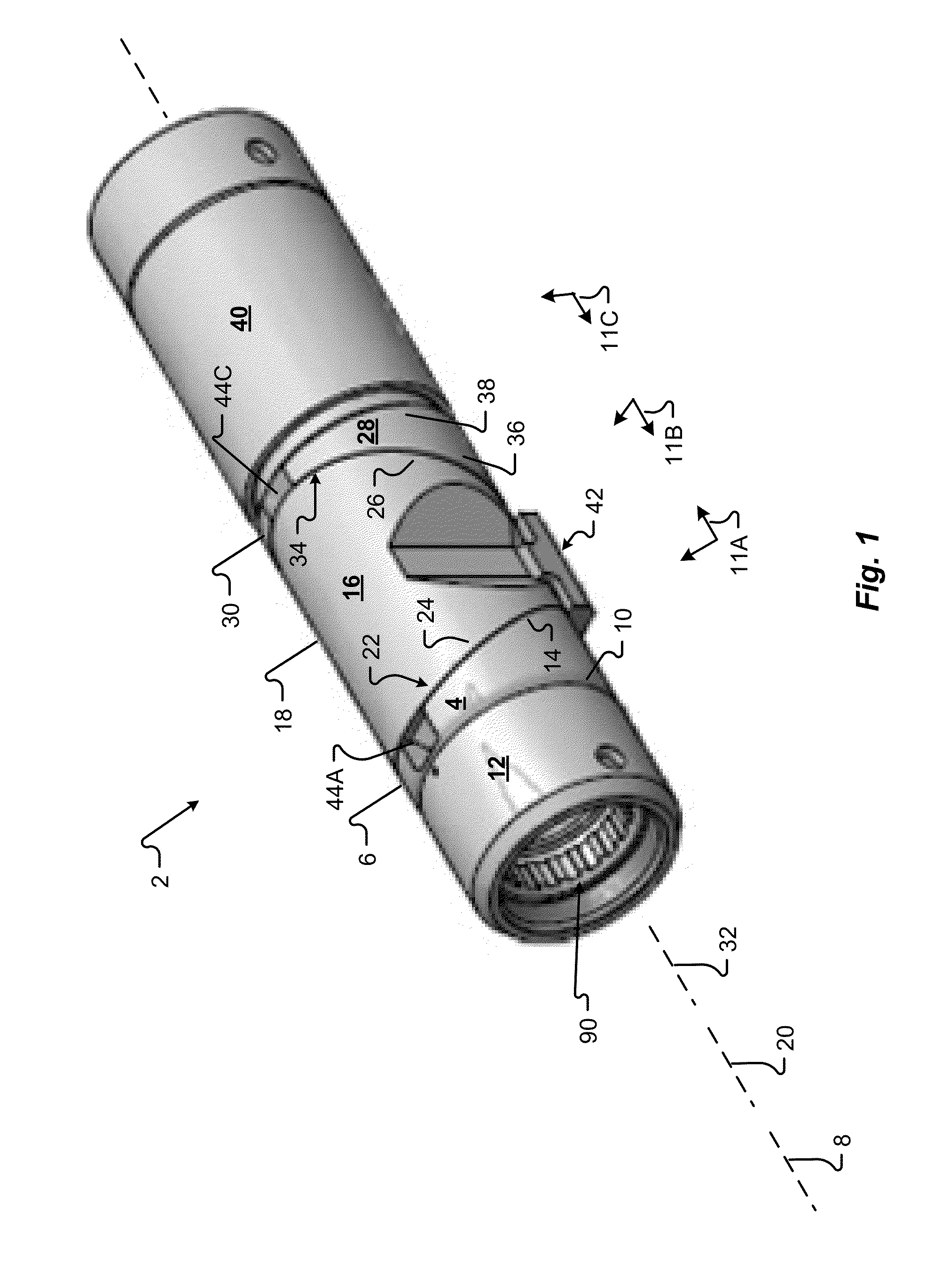
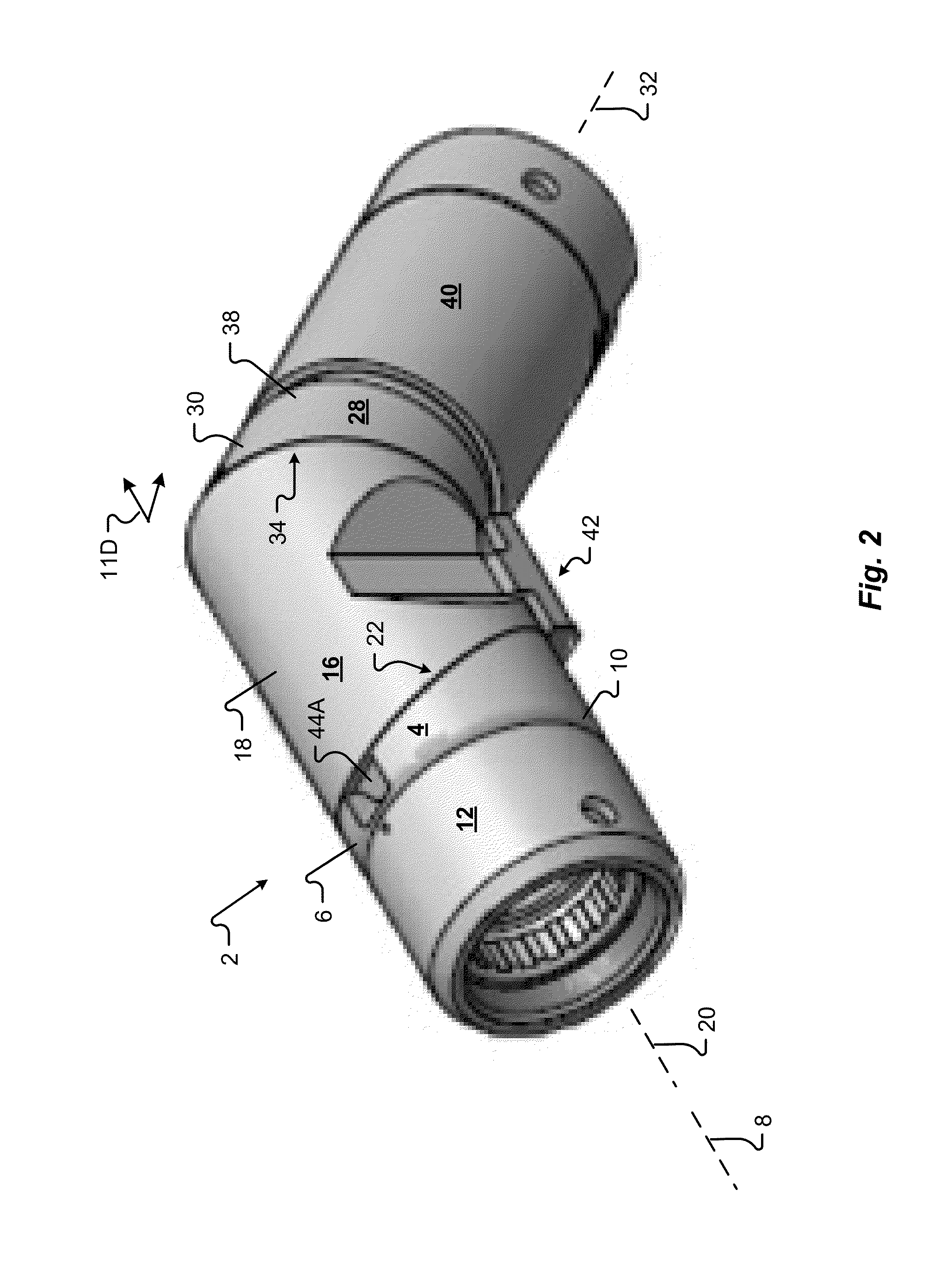
[0048]Referring now to FIG. 1, a rotatable cable assembly backshell 2 of one embodiment of the present invention is illustrated in a straight configuration. The backshell 2 has a connector piece 4 with a first cylindrical body 6 generally extending along a first longitudinal axis 8. The first cylindrical body 6 has a first hollow interior and a first end 10 oriented at an angle 11A of approximately 90° to the first longitudinal axis 8. The first end 10 is interconnected to a connector head or cable connector 12, which in FIG. 1 is adapted to interconnect to a fiber optic cable. Alternatively, a cable connector 12 adapted to interconnect to a copper cable may be interconnected to the cable assembly backshell 2. A cable adapter 90 of one embodiment of the present invention is interconnected to the cable connector 12. Cable adapters 90 of different configurations adapted to function with cables of different sizes and / or different types (such as fiber optic cables or copper cables) may ...


PUM

PropertyMeasurementUnit
angleaaaaaaaaaa
angleaaaaaaaaaa
angleaaaaaaaaaa

Abstract

Provided is a cable assembly backshell capable of three angular configurations: straight, 45°, and 90°. The backshell is designed to rotate at two joints that allow it to assume these three angular configurations. A locking mechanism is associated with the backshell which prevents unintended reconfigurations.

Description

[0001]This application claims the benefit of U.S. Provisional Patent Application Ser. No. 61 / 754,072, filed Jan. 18, 2013, the entire disclosure of which is incorporated by reference herein.FIELD OF THE INVENTION[0002]The embodiments of the present invention generally relate to backshell connectors used to interconnect a cable, wire, or fiber optic cable to an electrical component. One embodiment of the present invention is a cable assembly backshell having a connector piece, a union piece, and a cable entry piece.BACKGROUND[0003]Connectors that interconnect a cable, wire, or fiber optic cable to an electrical component frequently include a backshell. Those of skill in the art will appreciate that a “backshell” is a rear portion of a connector, which is normally separate from a connector head that interfaces with the electronic component. Backshells are used to secure the cable via a clamp to the end of the connector. More specifically, a connector backshell is designed to be placed...

Claims


Application Information

Patent Timeline
Patent Type & Authority Applications(United States)
IPC IPC(8): H01R43/00H01R13/58
CPCH01R13/506H01R13/5841H01R13/58H01R43/00Y10T29/49174Y10T29/49208Y10T29/49176Y10T29/4921H01R13/6581H01R13/533H01R43/26
Inventor KERN, RICHARD J.BUDD, NOLAN C.CAMARILLO, MATTHEW GUTHRIE
Owner R KERN ENG & MFG
Why Eureka
Try Eureka