Rotor for permanent magnet type motor, method of manufacturing rotor for permanent magnet type motor, and permanent magnet type motor
a technology of rotor and skew structure, which is applied in the direction of manufacturing stator/rotor bodies, magnetic circuit rotating parts, and shape/form/construction of magnetic circuits, etc., can solve the problems of short circuit magnetic flux in the axial direction caused by the skew structure becoming a factor of torque decrease, and suppressing torque decrease, so as to effectively reduce cogging torque
- Summary
- Abstract
- Description
- Claims
- Application Information
AI Technical Summary
Benefits of technology
Problems solved by technology
Method used
Image
Examples
first embodiment
Configuration of Permanent Magnet Type Motor
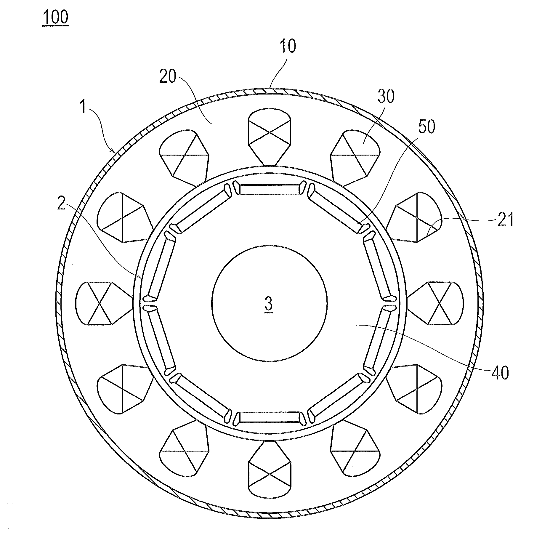
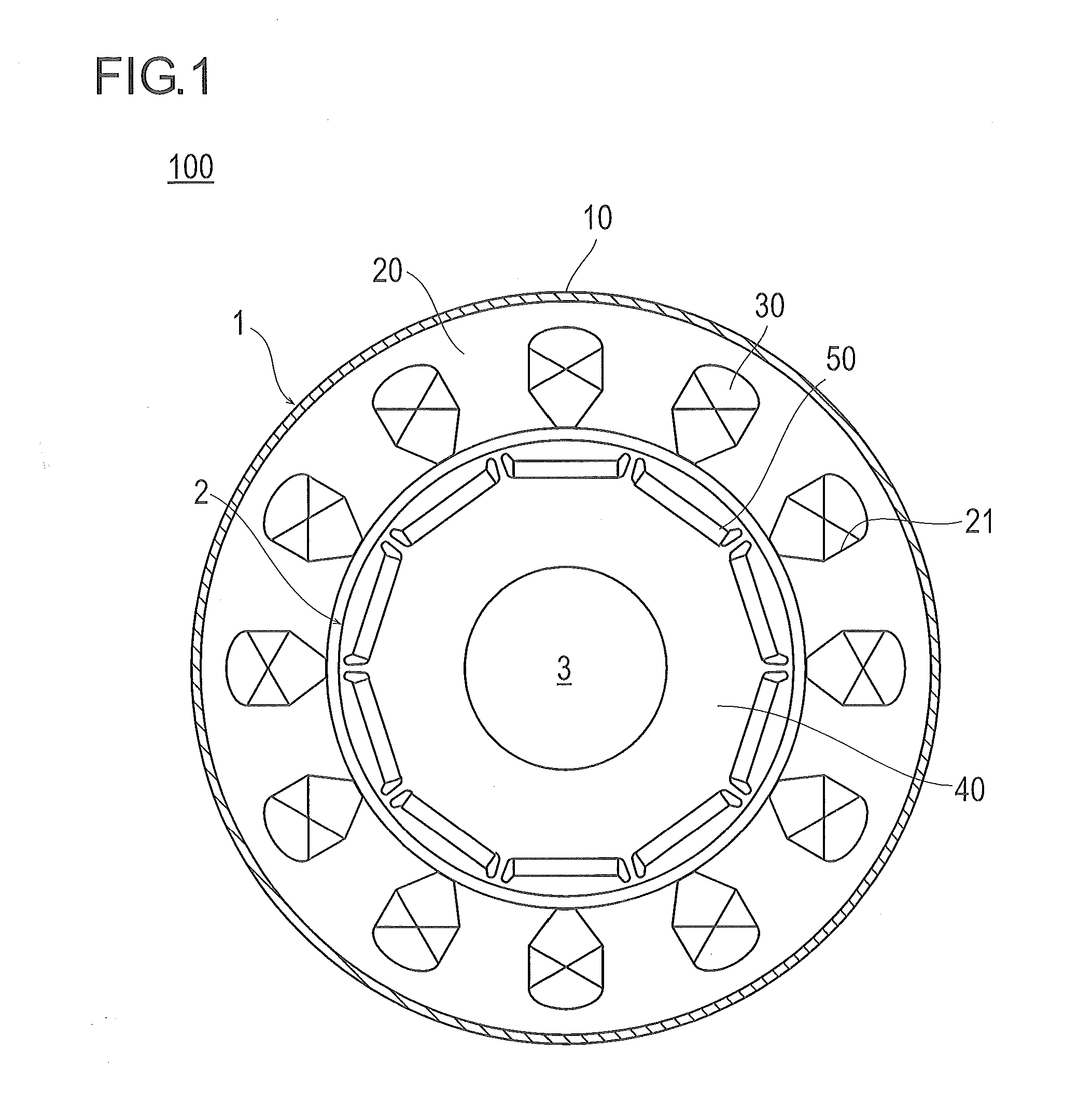
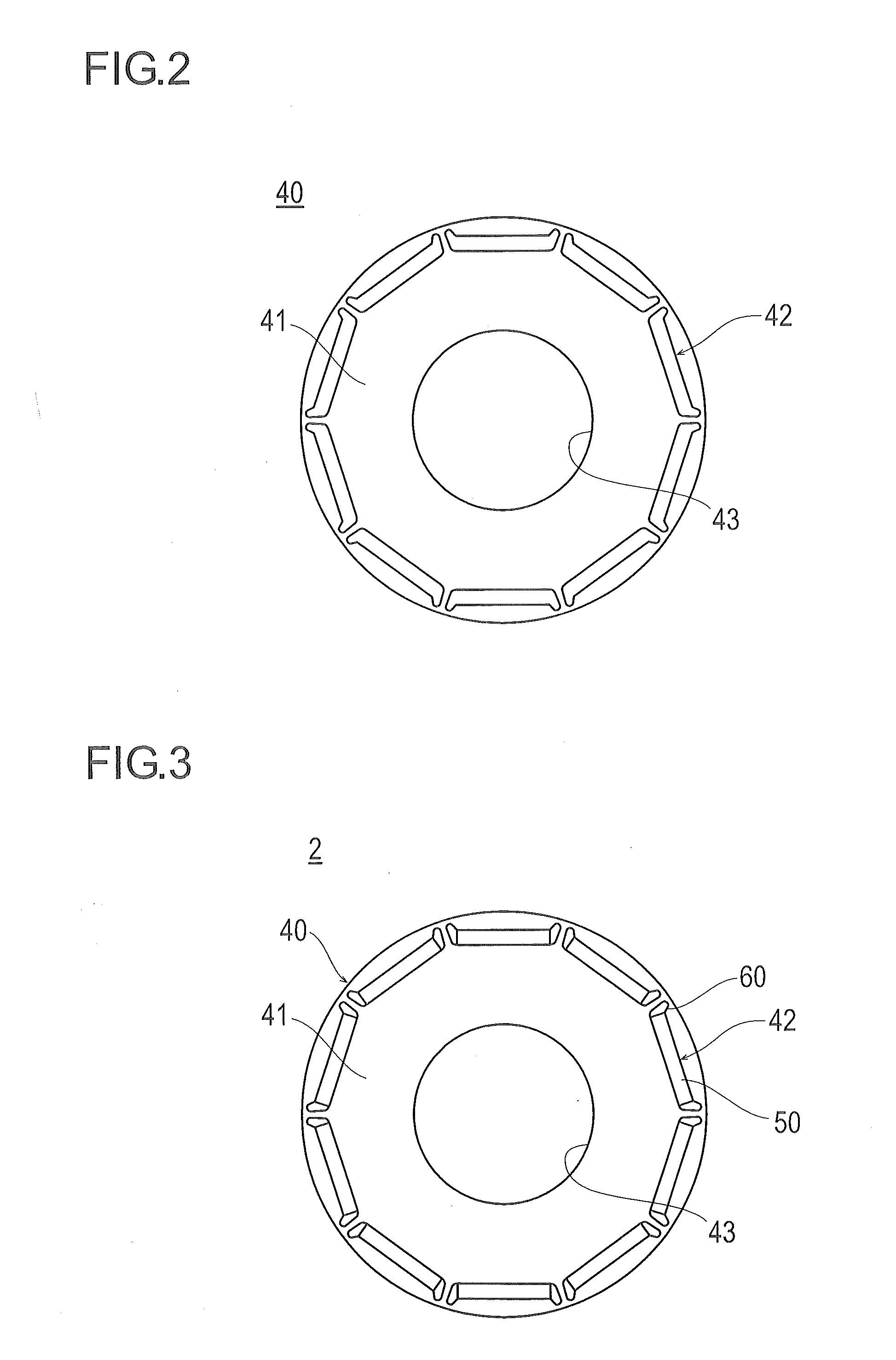
[0033]First, a configuration of the permanent magnet type motor according to a first embodiment will be described with reference to FIGS. 1 to 5. FIG. 1 is a schematic view of the overall configuration of the permanent magnet type motor according to the first embodiment. FIG. 2 is a schematic view of the cross-sectional shape of the rotor core. FIG. 3 is a schematic view of a state in which the permanent magnets are incorporated into the rotor core.
[0034]As the permanent magnet type motor of the first embodiment, for example, there is an interior permanent magnet motor (an IPM motor) in which a plurality of permanent magnets is incorporated into the interior of the rotor core. A permanent magnet type motor 100 illustrated in FIG. 1 is an IPM motor of 10 poles and 12 slots, and includes a stator 1 and a rotor 2.
[0035]As illustrated in FIG. 1, the stator 1 includes a yoke 10, a stator core 20, and a coil 30.
[0036]The yoke 10 is a cylindrical...
second embodiment
[0066]Next, a permanent magnet type motor according to a second embodiment will be described with reference to FIGS. 6 and 7. FIG. 6 is a perspective view of the rotor when a three-stage skew structure is provided in the same direction in the permanent magnet type rotor according to the second embodiment.
[0067]In FIG. 6, the rotor core is illustrated in a translucent manner so as to easily understand the state of the skew structure. FIG. 7 is an enlarged view of main parts when FIG. 6 is viewed from the axial direction. In FIG. 7, the front rotor core is illustrated in a translucent manner for clarity, and the permanent magnet is not illustrated. In addition, in FIGS. 6 and 7, the same components as those of the first embodiment will be described by denoting the same reference numerals.
[0068]As illustrated in FIG. 6, the second embodiment is different from the first embodiment in that the rotor 202 has a three-stage skew structure, and has a skew configuration in which the respectiv...
third embodiment
[0075]Next, a permanent magnet type motor according to a third embodiment will be described with reference to FIGS. 8 and 9. FIG. 8 is a perspective view of a rotor in a case in which a three-stage skew structure is provided and the skew directions are alternately inverted in the permanent magnet type rotor according to the third embodiment. In FIG. 8, the rotor core is illustrated in a translucent manner so as to easily understand the state of the skew configuration. FIG. 9 is an enlarged view of main parts when FIG. 8 is viewed from the axial direction. In FIG. 9, the front rotor core is illustrated in a translucent manner for clarity, and the permanent magnet is not illustrated. In FIGS. 8 and 9, the same components as those of the first embodiment will be described by denoting the same reference numerals.
[0076]As illustrated in FIG. 8, the third embodiment is different from the second embodiment in that the rotor 302 has a three-stage skew structure and the skew directions are a...
PUM
| Property | Measurement | Unit |
|---|---|---|
| Magnetic flux | aaaaa | aaaaa |
Abstract
Description
Claims
Application Information
 - R&D
- Intellectual Property
- Life Sciences
- Materials
- Tech Scout
- Unparalleled Data Quality
- Higher Quality Content
- 60% Fewer Hallucinations
Browse by: Latest US Patents, China's latest patents, Technical Efficacy Thesaurus, Application Domain, Technology Topic, Popular Technical Reports.
© 2025 PatSnap. All rights reserved.Legal|Privacy policy|Modern Slavery Act Transparency Statement|Sitemap|About US| Contact US: help@patsnap.com


