
Magnetron cathodes

a cathode and magneton technology, applied in the direction of discharge tube/lamp details, discharge tube main electrodes, discharge tube cathodes, etc., can solve the problem of output frequency shift, achieve the effect of reducing output frequency shift, facilitating the manufacturing of magnetron cathodes, and reducing output frequency

Active Publication Date: 2014-07-31
E2V TECH (UK) LTD
View PDF17 Cites 4 Cited by
  • Summary
  • Abstract
  • Description
  • Claims
  • Application Information

AI Technical Summary

Benefits of technology

The invention is about a new design for a magnetron cathode, which can be used in X-ray therapy and tomography applications. This design is more robust and rigid than previous versions, which means it can withstand movement and keep its output consistent, even when rotational stresses are involved. This is important because movements can cause variations in output, which can result in inconsistent dose delivery. The new design is also lighter than previous versions, which makes it easier to transport and maneuver. Additionally, the design includes a support structure made of molybdenum, which can reduce the generation of unwanted electrons from the surface, which could interfere with the magnetron's operation.

Problems solved by technology

Relative movement between components of a magnetron may result in shifts in output frequency and other undesirable results.

Method used


Image

  • Magnetron cathodes
  • Magnetron cathodes
  • Magnetron cathodes

Examples


Embodiment Construction

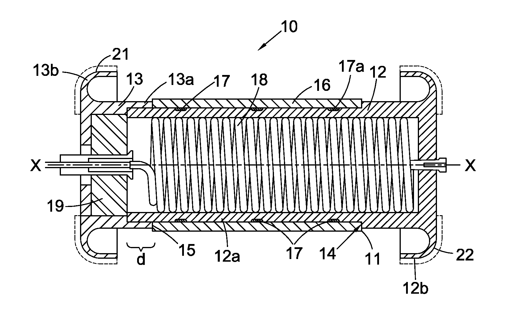
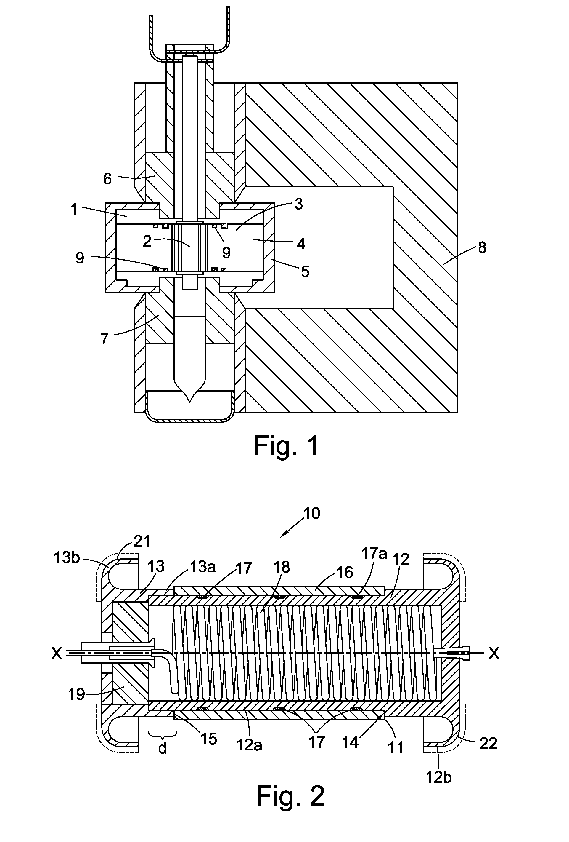
[0032]With reference to FIG. 2, a magnetron cathode 10 includes a support structure 11 having a longitudinal axis X-X and formed from a first part 12 and a second part 13. The first part 12 includes a first cylinder 12a integrally formed with a first end hat 12b. The second part 13 includes a second cylinder 13a integrally formed with a second end hat 13b. The first cylinder 12a is of greater longitudinal extent than the second cylinder 13a and has an external diameter that is smaller than the internal diameter of the second cylinder 13a. The two cylinders 12a and 13a overlap in the longitudinal direction by an amount d and are brazed together. The dimensions and braze material provide a secure joint between the first and second cylinders 12a and 13a.

[0033]The first cylinder 12a has a larger external diameter nearer the first end hat 13a to provide a step 14. The end of the second cylinder defines another step 15 which is of the same height in the radial direction as the first step...


PUM


Abstract

A magnetron cathode comprises electron emissive material included in a cathode body and a support structure for supporting the cathode body. The support structure has a longitudinal axis and includes a first part having a first cylinder integrally formed with a first end hat and a second part having a second cylinder integrally formed with a second end hat. The first cylinder and the second cylinder have an overlapping region in the longitudinal axial direction and are joined together. The cathode body is located around the first cylinder of the first part of the support structure and is joined to the first cylinder by a brazed joint. The outer surface of the first cylinder is grooved at the brazed joint.

Description

CROSS-REFERENCE TO RELATED APPLICATION[0001]This application claims the priority of Great Britain Patent Application GB 1216368.9, filed on Sep. 13, 2012, the subject matter of which is incorporated herein by reference.FIELD OF THE INVENTION[0002]This invention relates to magnetron cathodes and to magnetrons including such cathodes.BACKGROUND[0003]Magnetrons are devices for generating high frequency power. In one type of magnetron, a cathode is surrounded by an anode in a generally coaxial arrangement. The anode includes resonant anode cavities which may, for example, be defined by a plurality of radially extending anode vanes or by some other configuration and the space between the cathode surface and the anode vane tips provides an interaction space. In operation, an electrical field is established between the anode and the cathode and a magnetic field is provided transverse to the electric field. Electrons emitted from the cathode are acted on by the electric and magnetic fields....

Claims


Application Information

Patent Timeline
Patent Type & Authority Applications(United States)
IPC IPC(8): H01J23/05H01J25/50
CPCH01J25/50H01J23/05H01J25/587
Inventor ROBERTS, CLIVELODGE, ROBERT CHARLES
Owner E2V TECH (UK) LTD
Learn More