Method and system for real-time lens flare rendering

a real-time lens and rendering technology, applied in the field of real-time lens flare rendering, can solve the problems of insufficient visual quality for small computation time, inability to interact (e.g., zooming), etc., and achieve the effect of efficient rendering of realistic lens flares

Inactive Publication Date: 2014-07-31
MAX PLANCK GESELLSCHAFT ZUR FOERDERUNG DER WISSENSCHAFTEN EV +1
View PDF5 Cites 5 Cited by
  • Summary
  • Abstract
  • Description
  • Claims
  • Application Information

AI Technical Summary

Benefits of technology

[0008]It is therefore an object of the present invention to provide an improved method and system for efficiently rendering realistic lens flares.SUMMARY OF THE INVENTION

Problems solved by technology

In none of these cases however, an underlying camera or lens model was considered.
Furthermore, the visual quality for small computation times can be insufficient, making interaction (e.g., zooming) impossible.

Method used


Image

  • Method and system for real-time lens flare rendering
  • Method and system for real-time lens flare rendering
  • Method and system for real-time lens flare rendering

Examples


Embodiment Construction

[0022]The main idea behind the inventive technique is not only to consider individual rays, but to exploit a strong coherence of rays within lens flare, in the sense of choosing rays underlying the same interactions with the optical system.

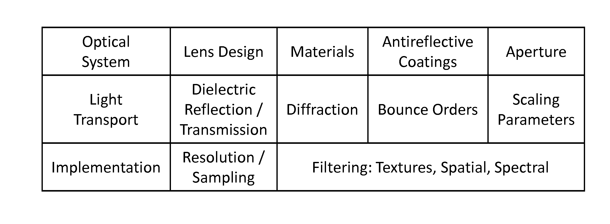
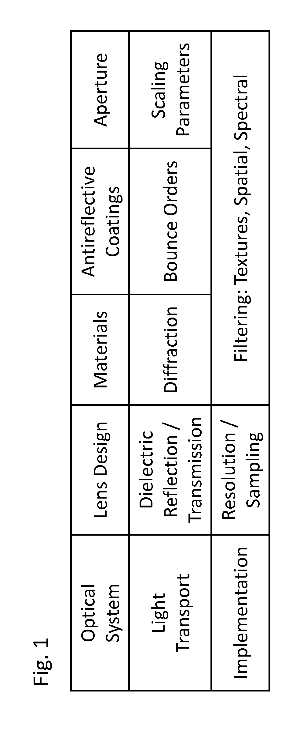
[0023]FIG. 1 is a block diagram showing different aspects of optical systems considered by the invention. Generally, an optical system may comprise lenses and an aperture, each lens having a specific design, material and possibly, coating. Light propagation is governed by light transmission, and reflection at the set of lens surfaces and characteristic planes (entrance, aperture and sensor plane).

[0024]Specific lens designs of a given optical system may be modeled geometrically as a set of algebraically defined surfaces, i.e., spheres and planes. In terms of materials or optical media, it is sufficient for a method according to the present embodiment of the invention to consider perfect dielectrics with a real-valued refractive index. All optical ...


PUM


Abstract

A method and device for efficiently simulating lens flares produced by an optical system is provided. The method comprises the steps of—Simulating paths of rays from a light source through the optical system, the rays representing light; and Estimating, for points in a sensor plane, an irradiance, based on intersections of the simulated paths with the sensor plane.

Description

[0001]The present invention relates to a method and a system for real-time lens flare rendering.TECHNICAL BACKGROUND[0002]Lens flare is an effect caused by light passing through a photographic lens in any other way than the one intended by design, most importantly through interreflection between optical elements. Flare becomes most prominent when a small number of very bright lights are present in a scene. In traditional photography and cinematography, lens flare is considered a degrading artifact and therefore undesired. Among the measures to reduce flare in an optical system are optimized barrel designs, antireflective coatings, and lens hoods.[0003]On the other hand, flare or flare-like effects have often been used deliberately to achieve an increase in realism or perceived dynamic range. Many image and video editing packages feature filters for the generation of “flare” effects, and in video games the effect is just as popular. In the production of computer-generated feature mov...

Claims


Application Information

Patent Timeline
Patent Type & Authority Applications(United States)
IPC IPC(8): G06T11/00
CPCG06T11/001G06T15/50G06T15/06G02B27/0012
Inventor HULLIN, MATTHIASLEE, SUNGKILSEIDEL, HANS-PETEREISEMANN, ELMAR
Owner MAX PLANCK GESELLSCHAFT ZUR FOERDERUNG DER WISSENSCHAFTEN EV
Why Eureka
Try Eureka