
Weatherproof Windscreen for Microphone

a windscreen and microphone technology, applied in the field of weatherproof windscreens for microphones, can solve the problems of lack of after-market supplemental windscreens, design that is waterproof or water-resistant, and affecting the sound quality of the microphone, so as to prevent damage by small animals, enhance the integrity of the fabric, and sacrifice the effect of audio quality

Inactive Publication Date: 2014-07-31
PIELSTICKER WILLIAM J
View PDF1 Cites 10 Cited by
  • Summary
  • Abstract
  • Description
  • Claims
  • Application Information

AI Technical Summary

Benefits of technology

The patent is about a windscreen designed to protect microphones and other wind-sensitive equipment from weather. The windscreen is made up of a sealed chamber made of water-proof fabric sealed with a foam covering, which also uses a layer of foam to prevent noise. The windscreen can be enclosed within a structure to protect it from damage by small animals. The design also allows for effective protection for boundary microphones and other microphone-containing devices in various weather conditions for extended periods of time with minimal impact on sensitivity. Overall, the patent provides an improved solution for protecting sensitive equipment from wind-related damage.

Problems solved by technology

Boundary microphones also are especially well suited to transmit a wide range of frequencies from near and distant sources while not altering the frequency of distant sounds, typically a problem for conventional microphones.
Boundary microphones generally are intended for indoor use and not designed to be waterproof or water-resistant.
Boundary microphones generally have a cursory windscreen element, and lack an after-market choice of supplemental windscreens from suppliers like WindTech™.
Akino also claims some wind noise dampening through the electrostatic flocking layer.
While Akino's design is aimed at outdoor security monitoring, it is unclear how well this could be applied to locations fully exposed to the elements.
He also notes that problems arise should the foam windsock become waterlogged, limiting its utility for outdoor use.

Method used


Image

  • Weatherproof Windscreen for Microphone
  • Weatherproof Windscreen for Microphone
  • Weatherproof Windscreen for Microphone

Examples


Embodiment Construction

:

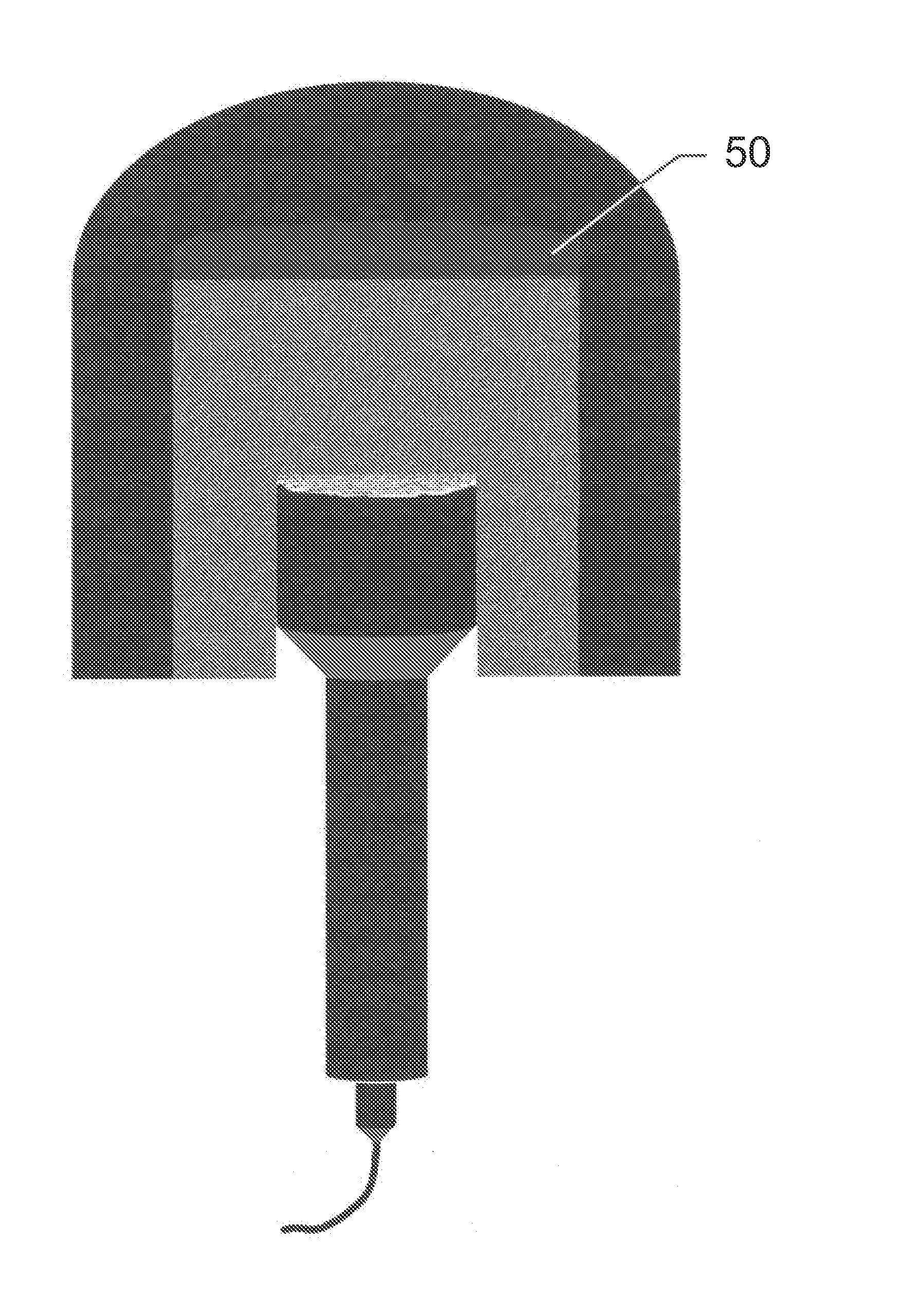
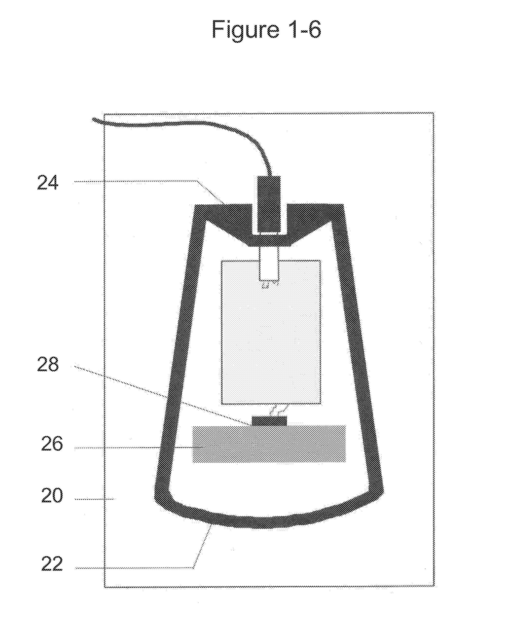
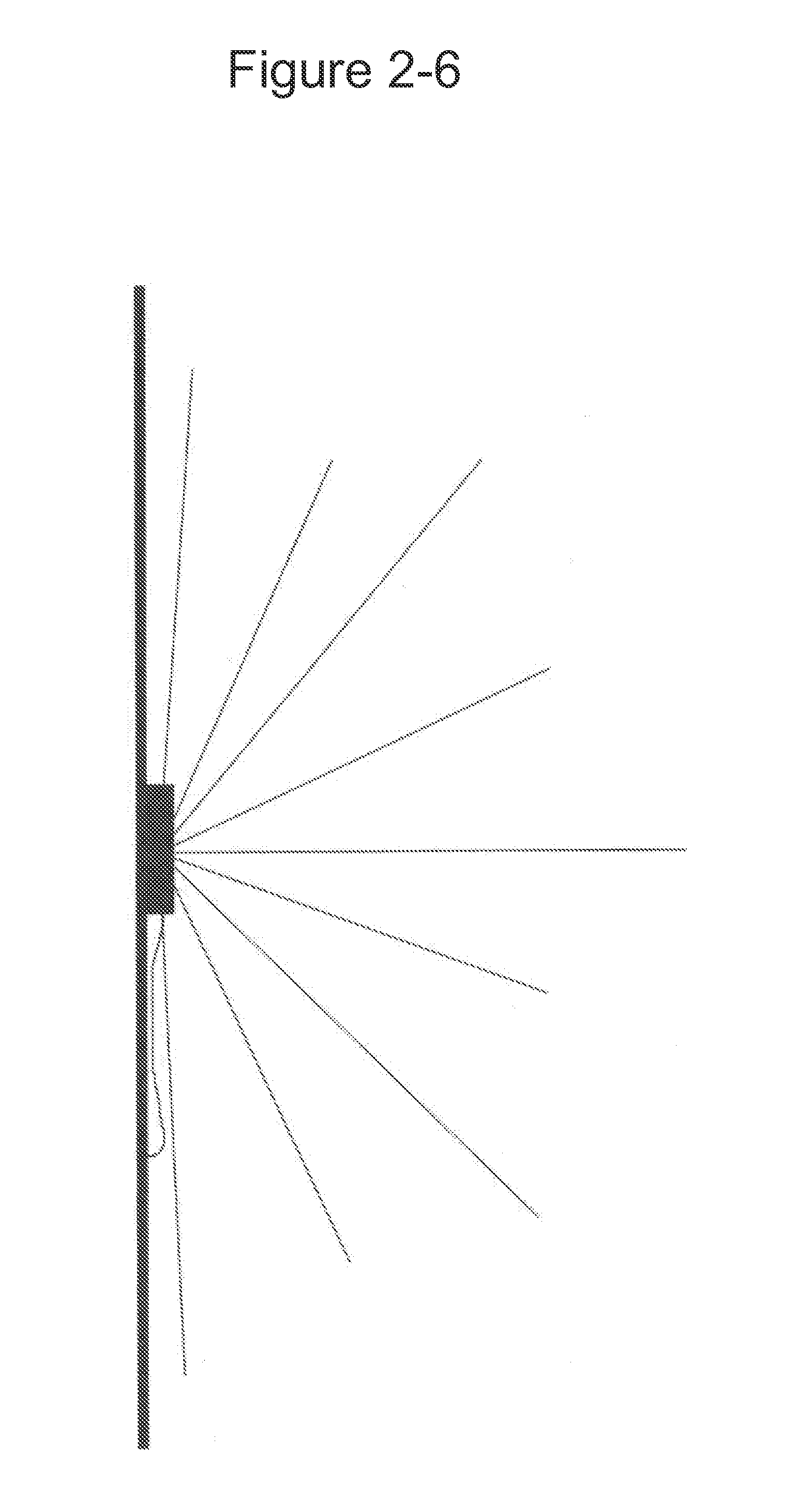
[0009]Depicted in FIG. 1 is a Peavey PSM-3 boundary microphone with a flat-bottomed housing viewed with its perforated metal cover removed. The boundary microphone's half-omnidirectional pick-up pattern (FIG. 2) allows a windscreen to be confined to the surface above the microphone body. As this common style of boundary microphone generally lacks any commercial windscreen options, a custom high-wind windscreen must be constructed. Accordingly, an internal base is configured for the microphone and inner foam windscreen 20.

[0010]The base material can vary but should be fairly rigid, thin, and flat. Preferably, a piece of 4-ply mat board 20 (but other thin materials can be used) is cut in a square, rectangle or another shape similar to the outline of the microphone housing, allowing enough room around the base of the of the microphone housing to anchor a layer of acoustic foam or ½″ min. from the closest point of the housing. The microphone is positioned on the base centrally from lef...


PUM


Abstract

A sealed enclosure providing a microphone contained therein extended protection from the weather and some other outdoor hazards while not substantially altering the dynamic range of said microphone. The enclosure consists of a layer of liquid-water impermeable fabric, a layer of acoustical foam, a protective cage, and a wind noise dampening external cover. The enclosure is assembled around a microphone and a commercial foam windscreen, or around a custom high-wind foam windscreen first assembled around the microphone. As such, the weatherproof enclosure enables continuous use of boundary microphones and many other types and styles of microphones outdoors year round while supplementing the wind noise reduction of the enclosed foam windscreen.

Description

BACKGROUND OF THE INVENTION:[0001]Since 1977, researchers and environmentalists have used the term “soundscape” to describe the “acoustic ecology” of a locale. Any effort to electronically monitor a soundscape, such as the audio environment of a particular geographic area or even one's backyard, would be best served by using one or more boundary microphones. Boundary microphones have a semi-omnidirectional pick-up pattern. Mounting a boundary microphone on a flat surface will augment the pick-up capability of the microphone (extends the boundary), but only in the direction above the surface. When mounted on a vertical surface, a boundary microphone will receive and transmit all audible sounds in the direction “above” that surface. When boundary microphones are used outdoors, vertical mounting enables the pickup of all sounds from ground to sky in front of the surface, and virtually no sounds from behind it. Boundary microphones also are especially well suited to transmit a wide rang...

Claims


Application Information

Patent Timeline
IPC IPC(8): H04R1/08
CPCH04R2410/07H04R1/086
Inventor PIELSTICKER, WILLIAM J
Owner PIELSTICKER WILLIAM J
Learn More