Machining unit for a program-controlled machine tool

a technology of program-controlled machine tools and machining units, which is applied in the direction of manufacturing tools, metal-working machine components, positioning apparatuses, etc., can solve the problems of faulty machining operations, tool runs out of true, and spindle head deformation, etc., and achieves the effect of easy and fast way

Active Publication Date: 2014-07-31
DECKEL MAHO PFRONTEN GMBH
View PDF13 Cites 12 Cited by
  • Summary
  • Abstract
  • Description
  • Claims
  • Application Information

AI Technical Summary

Benefits of technology

[0012]An advantage of this concept is that the outer ring and also the inner annular body can be removed and installed in an easy and fast way separately or also jointly. As op...

Problems solved by technology

Particular problems will result when chips and other contaminations stick to the usually finished surface pairs of tool cone and tool holder or the front-side plane surfaces, or both, and these accumulated chips are pressed in firmly when the tool is exchanged the next time.
Since the clamping forces applied to the tool shafts by the clamping devices of the work spindle can reach extremely high values, chips clamped between the inner wall of the tool holder and the outer wall of the tool shaft cause minor deformations of the spindle head, which can be the reason why the tool runs out of true and can be the cause of other faulty machining operations.
In addition, similar problems may occur when the finished plane surfaces have minor defects or also chip deposits on the front side of the tool holder, which can be made as full areas or also subareas.
As a result, the tool axis is tilted or offset with respect to the spindle central axis by small amounts...

Method used


Image

  • Machining unit for a program-controlled machine tool
  • Machining unit for a program-controlled machine tool
  • Machining unit for a program-controlled machine tool

Examples


Embodiment Construction

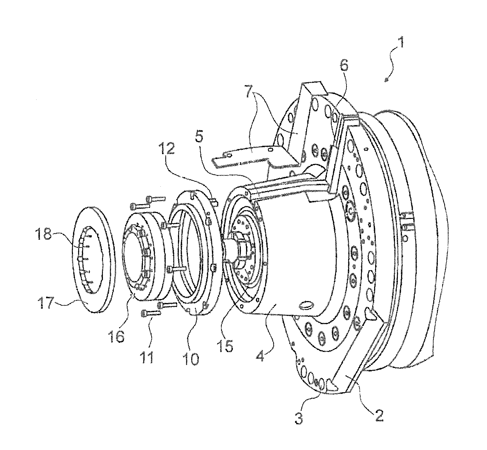
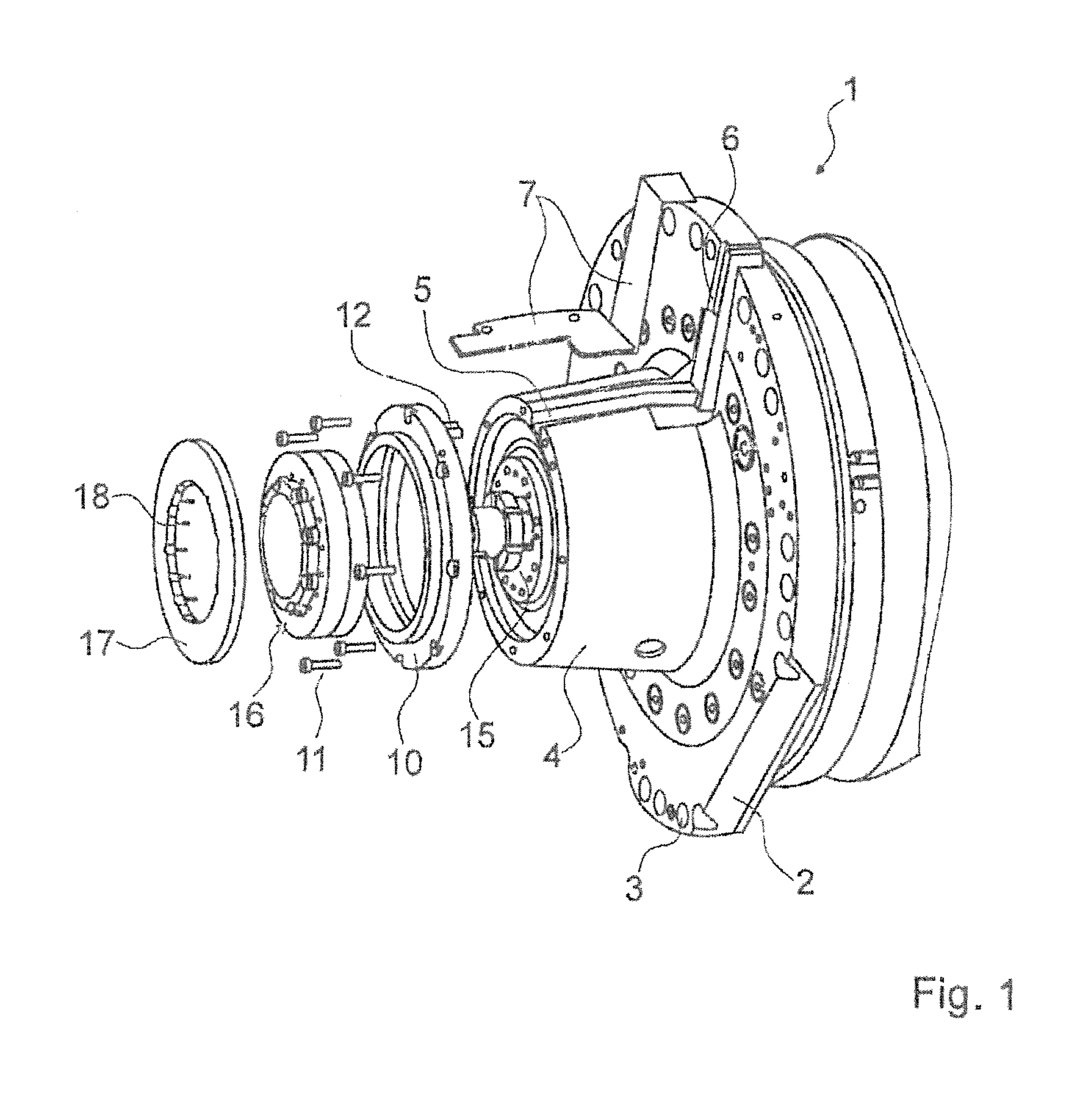
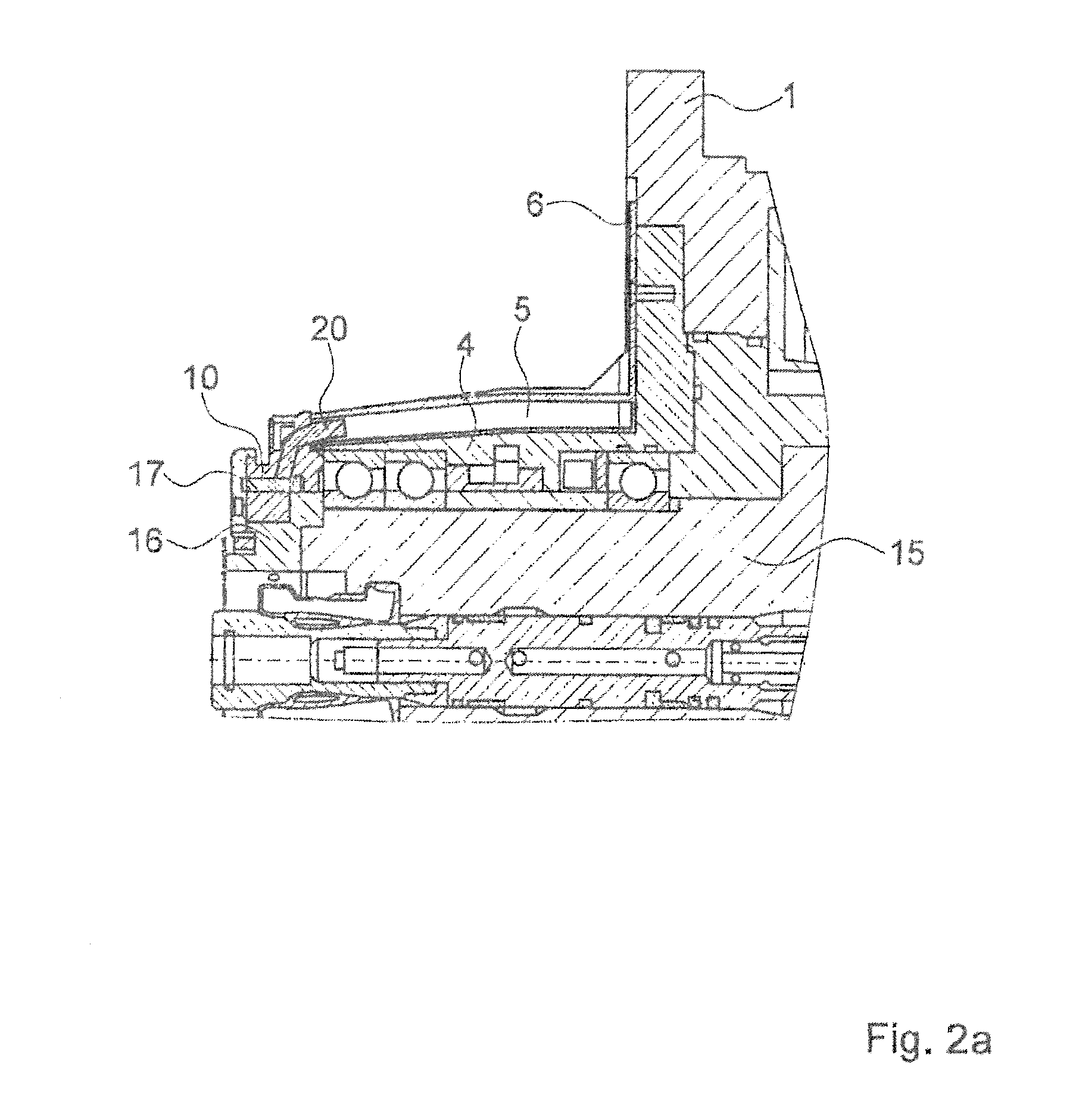
[0008]A purpose of the invention embodiments disclosed herein is to provide a machining unit of the above mentioned type, wherein the maintenance and repair of the measuring and monitoring device allows the separate determination of changes in the form of the milling head in the circumferential direction and additionally also deviations of the coaxial orientation of the tool axis with respect to the spindle axis. Further, the effort regarding the installation and removal of the measuring and monitoring apparatus in the work spindle is simplified compared with known apparatus.

[0009]Improved measuring accuracy is achieved by the use of two different sensor types which act as “axial” sensors on the one hand, and as “radial” sensors on the other hand. The “axial” sensors detect the axial pressure applied to the mating surface of the spindle head by the abutment ring of the tool shaft, that pressure being generated by the forces of the activated collet. Since in each case a plurality of ...


PUM

PropertyMeasurementUnit
Energyaaaaaaaaaa

Abstract

A machining unit for a program-controlled machine tool having a measuring and monitoring device for monitoring the position and condition of a tool shaft in the tool holder. This measuring and monitoring device includes a plurality of axial sensors and radial sensors and an evaluating unit for the measurement results detected by the sensors. An outer ring is releasably fastened to the spindle housing and contains an electronic transmission element and terminals for energy and data cables. A rotor is assigned to this stationary outer ring and contains the sensors and is coupled to the outer ring for the non-contact data transmission. The rotor is releasably fastened to the front end face of the spindle by bolted connections.

Description

FIELD OF INVENTION[0001]The invention embodiments relate to a machining unit for a program-controlled machine tool, and more particularly to such a machining unit having a measuring device on the work spindle for monitoring the position and condition of a tool shaft inserted in the tool holder, wherein the measuring device has a plurality of sensors and an evaluating unit for the measurement results of the sensors.BACKGROUND OF THE INVENTION[0002]The individual and also serial machining of workplaces in modern cutting machine tools calls for maximum accuracies and the strict observance of closest tolerance ranges. In order to achieve and observe these high specifications, the components involved in the machining process, that is, the workpieces including their workpiece carriers (pallets) and also the tools including their tool holders and the work spindles, must be positioned and locked with high precision. The chips which are produced during the machining operation by the tool and...

Claims


Application Information

Patent Timeline
IPC IPC(8): B23Q17/00
CPCB23Q17/002B23Q1/0009B23Q3/12B23Q2017/001B23Q17/0966Y10T409/30084Y10T409/306832Y10T409/309352B23Q15/14B23Q17/22
Inventor VEITTINGER, HANS
Owner DECKEL MAHO PFRONTEN GMBH
Why Eureka
Try Eureka